box device

A technology of installation position and vehicle box, which is applied in the box device field of SCR box, can solve problems such as leakage at the floating valve, achieve reliable ventilation, and prevent crystal formation and leakage

Active Publication Date: 2020-07-14
MAGNA STEYR FUEL SYST
View PDF6 Cites 0 Cited by
  • Summary
  • Abstract
  • Description
  • Claims
  • Application Information

AI Technical Summary

Problems solved by technology

[0005] However, leaks may occur at the float valve as residues of the tank contents dry out at the movable float while the associated crystals form

Method used


Image

  • box device

Examples


Embodiment Construction

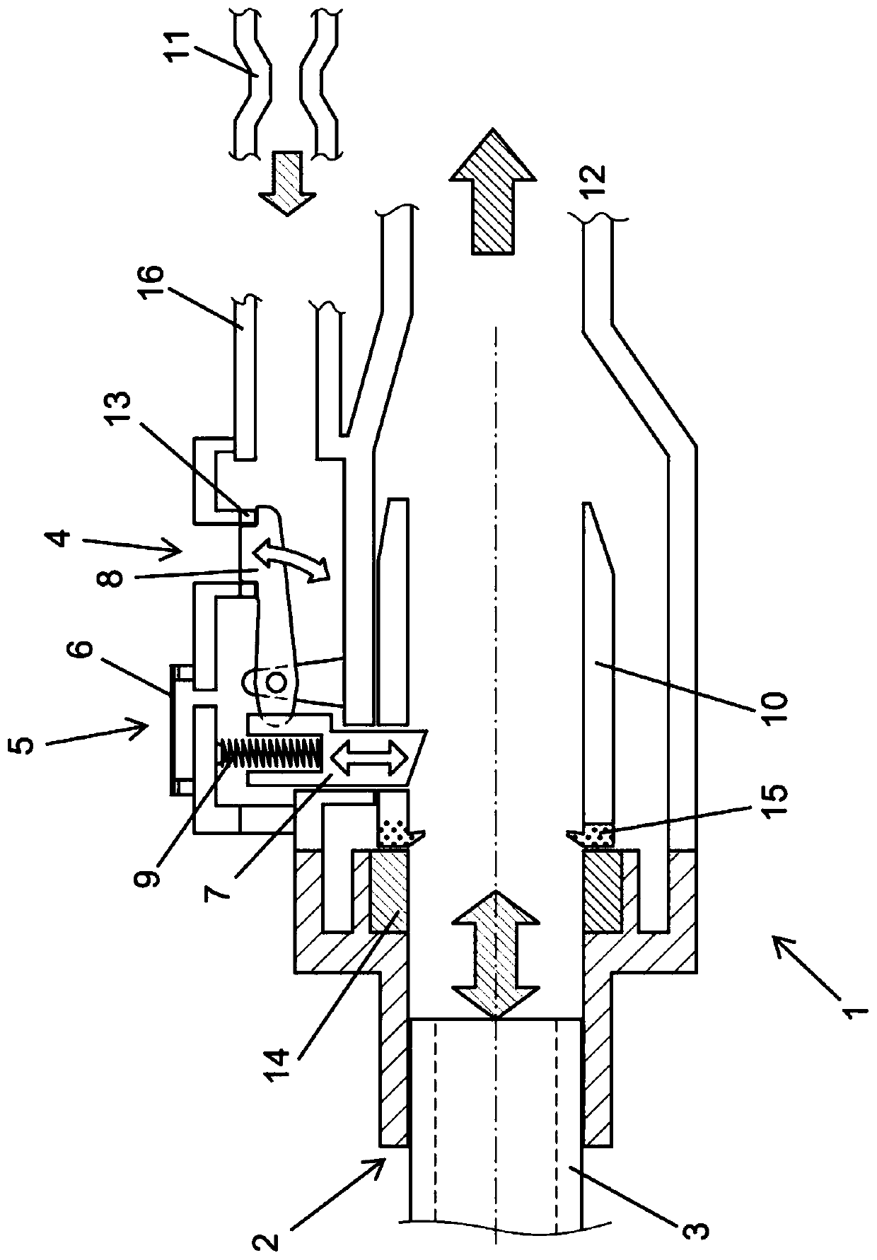
[0024] The box device according to the invention is in figure 1 shown in , which is provided as a motor vehicle tank for filling an SCR tank, in particular a urea tank.

[0025] The tank arrangement comprises, in addition to the motor vehicle tank (not shown), a filling head 1 for filling the motor vehicle tank, which forms a connection to the filling pipe 12 in the region of the indicated arrow at the right end of the filling head 1 . Transition Department.

[0026] In the fill tube head 1's figure 1 The left end of the is provided with a filling opening 2 for introducing a nozzle 3 to fill the motor vehicle tank through the nozzle 3.

[0027] The filling opening 2 of the filling nozzle 1 forms a transition to the flow guiding device 10 via an annular magnet 14 and a likewise radial lip seal 15 .

[0028] During the introduction of the nozzle 3, the filling ventilation opening 4 is open, the filling ventilation opening 4 is formed radially on the outside of the flow guidin...


PUM


Abstract

The invention discloses a tank device for a motor vehicle, comprising a motor vehicle tank, a filling nozzle (1) for filling the motor vehicle tank and a ventilation outlet, wherein the filling nozzle (1) includes a nozzle (3 ) to fill the filling opening (2) and the filling ventilation opening (4) of the motor vehicle tank through the nozzle (3); wherein the filling ventilation opening (4) is open during the introduction of the nozzle (3), so that the filling nozzle The interior space of (1) is fluidly connected to the vent outlet via the fill vent opening (4); wherein the fill vent opening (4) is closed during removal of the nozzle (3) from the fill opening (2); wherein the fill tip ( 1) Comprising an operative vent opening (5) with a semi-permeable membrane (6) that enables gas to pass through the operative vent opening (5) and prevents fluid passage; wherein the operative vent opening (5) is fluidly connected to the vent Export, also discloses a motor vehicle having such a box arrangement.

Description

technical field [0001] The invention relates to a tank arrangement for a motor vehicle, in particular for an SCR tank (Selective Catalytic Reduction). Background technique [0002] Tank arrangements, in particular SCR tanks for motor vehicles, are known per se. In addition to the motor vehicle tank itself, they may include a filling device with a filling pipe and a filling nozzle for filling the motor vehicle tank through a nozzle, and a ventilation device with a device for venting gases to the vehicle surrounding ventilation outlets. [0003] It is precisely in the case of SCR tanks, such as in particular urea tanks for exhaust gas aftertreatment, that it is difficult to create suitable ventilation. Filling of such tanks can take place via nozzles at high filling speeds of up to 40 L / min on the one hand and also via simple tanks such as Kruse bottles on the other hand. This type of filling requires a flexible ventilation system for the tank arrangement, which is also abl...

Claims


Application Information

Patent Timeline
Patent Type & Authority Patents(China)
IPC IPC(8): F01N3/20B60K13/04
CPCB60K13/04F01N3/2066F01N2610/1486F01N2610/1406F01N2610/02B60K15/04F01N2610/1413F01N2610/1466
Inventor J.格罗斯
Owner MAGNA STEYR FUEL SYST
Why Eureka
Try Eureka