IPM Rotor, IPM Rotor Manufacturing Method and IPM Rotor Manufacturing Apparatus

a technology of ipm rotor and manufacturing method, which is applied in the direction of manufacturing stator/rotor body, magnetic circuit rotating parts, magnetic circuit shape/form/construction, etc. it can solve the problems of low fluidity and insufficient filling of gaps with resin, so as to achieve enhanced coupling rigidity between magnet and core body attained by holding members, the effect of sufficient filling and filling

Active Publication Date: 2009-11-12
TOYOTA JIDOSHA KK
View PDF10 Cites 20 Cited by
  • Summary
  • Abstract
  • Description
  • Claims
  • Application Information

AI Technical Summary

Benefits of technology

[0008]In the apparatus for manufacturing the IPM rotor structured as described above, a plurality of inlets are provided and, therefore, it is possible to sufficiently fill the gap between the magnet and the inner wall of the slot with the filler. Consequently, coupling rigidity between the magnet and the core body can be enhanced, and NV characteristics of the IPM rotor can be improved.
[0009]Preferably, the slot is formed at a position spaced in a radial direction from a rotation axis of the core body. The gap includes an inner circumferential portion formed inner than the magnet and an outer circumferential portion formed outer than the magnet with the rotation axis being the center. The filler is injected to the inner circumferential portion and the outer circumferential portion through the plurality of inlets. In the apparatus for manufacturing the IPM rotor structured as described above, particularly the inner circumferential portion and the outer circumferential portion of the gap can sufficiently be filled with the filler. Consequently, the magnet can more reliably be held on the core body against centrifugal force acting on the magnet when the core body rotates.
[0011]Preferably, the gap includes a first side and a second side extending in mutually different directions along the outer circumference of the magnet and a corner portion where the first side and the second side intersect with each other. The filler is injected to the corner portions through the plurality of inlets. In the apparatus for manufacturing the IPM rotor structured as described above, the filler is introduced to the corner portion where the fluidity of the filler injected to the gap lowers significantly. Therefore, sufficient filling with the filler becomes possible.
[0013]By the method of manufacturing the IPM rotor as described above, the filler is introduced to the gap at a plurality of portions displaced in the circumferential direction along which the gap extends, and therefore, sufficient filling with the filler becomes possible. Consequently, coupling rigidity between the magnet and the core body is enhanced, and NV characteristics of the IPM rotor can be improved.
[0014]Preferably, the step of injecting the filler includes the steps of placing a solid filler on the end surface, and causing the filler to flow into the gap by melting the solid filler. As the filler flows to the gap because of the weight of itself, sufficient filling is difficult. Therefore, the method of manufacturing the IPM rotor of the present invention as described above is effectively applied, as the filling characteristic of the filler can be improved by the present invention.
[0016]By the IPM rotor structured as described above, the filler is injected to the gap from a plurality of portions along the opening edge of the slot, and hence, sufficient filling with the filler becomes possible. Consequently, coupling rigidity between the magnet and the core body attained by the holding member is enhanced, and the NV characteristics of the IPM rotor can be improved.

Problems solved by technology

The resin, however, has low fluidity and, therefore, it is possible that the gap is not fully filled with the resin.

Method used


Image

  • IPM Rotor, IPM Rotor Manufacturing Method and IPM Rotor Manufacturing Apparatus
  • IPM Rotor, IPM Rotor Manufacturing Method and IPM Rotor Manufacturing Apparatus
  • IPM Rotor, IPM Rotor Manufacturing Method and IPM Rotor Manufacturing Apparatus

Examples


embodiment 1

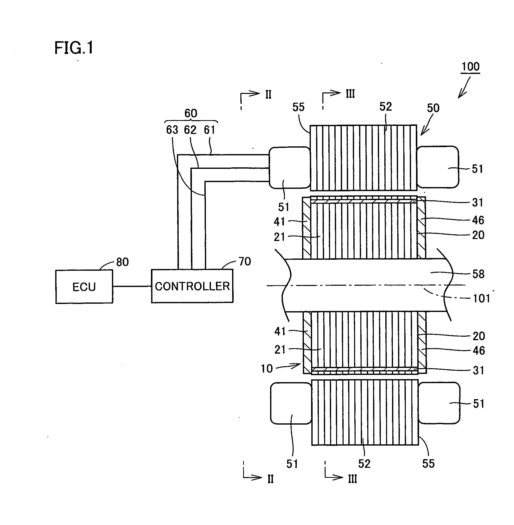
[0035]FIG. 1 is a cross-sectional view schematically showing a motor installed in a hybrid vehicle. The hybrid vehicle having the motor installed shown in this figure uses, as power sources, an internal combustion engine such as a gasoline engine or a diesel engine, and a rechargeable secondary battery (battery).

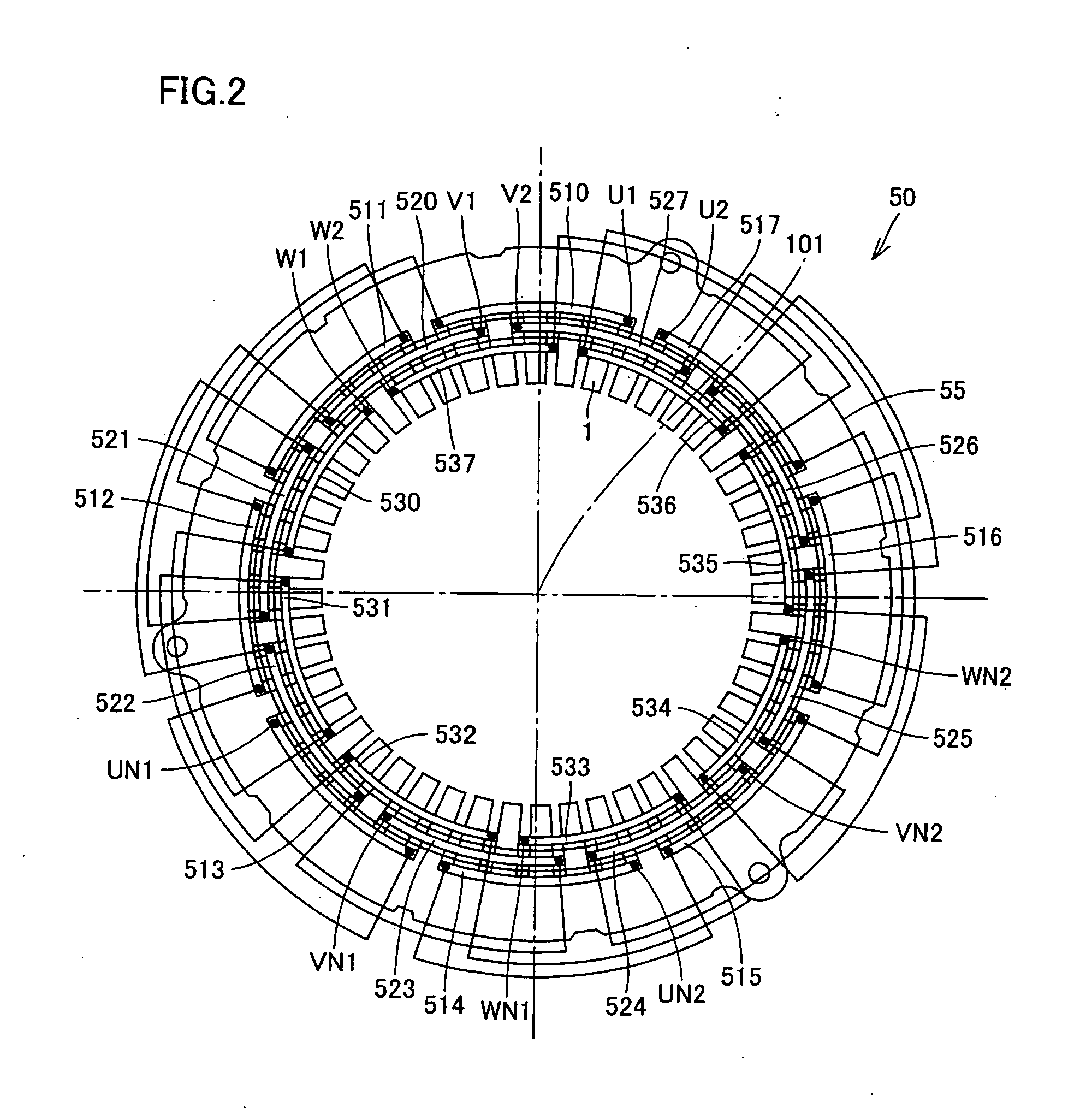
[0036]Referring to FIG. 1, a motor 100 includes an IPM rotor 10 and a stator 50 arranged on an outer circumference of IPM rotor 10. IPM rotor 10 is provided on a shaft 58 extending along a central axis 101. Shaft 58 rotates, together with IPM rotor 10, about the central axis 101.

[0037]IPM rotor 10 includes a rotor core 20, a permanent magnet 31 embedded in rotor core 20, and a holding member, not shown, for holding permanent magnet 31 on rotor core 20. Rotor core 20 has a cylindrical shape extending along the central axis 101. Rotor core 20 includes a plurality of magnetic steel sheets stacked in the axial direction of central axis 101.

[0038]Stator 50 includes a stator core ...

embodiment 2

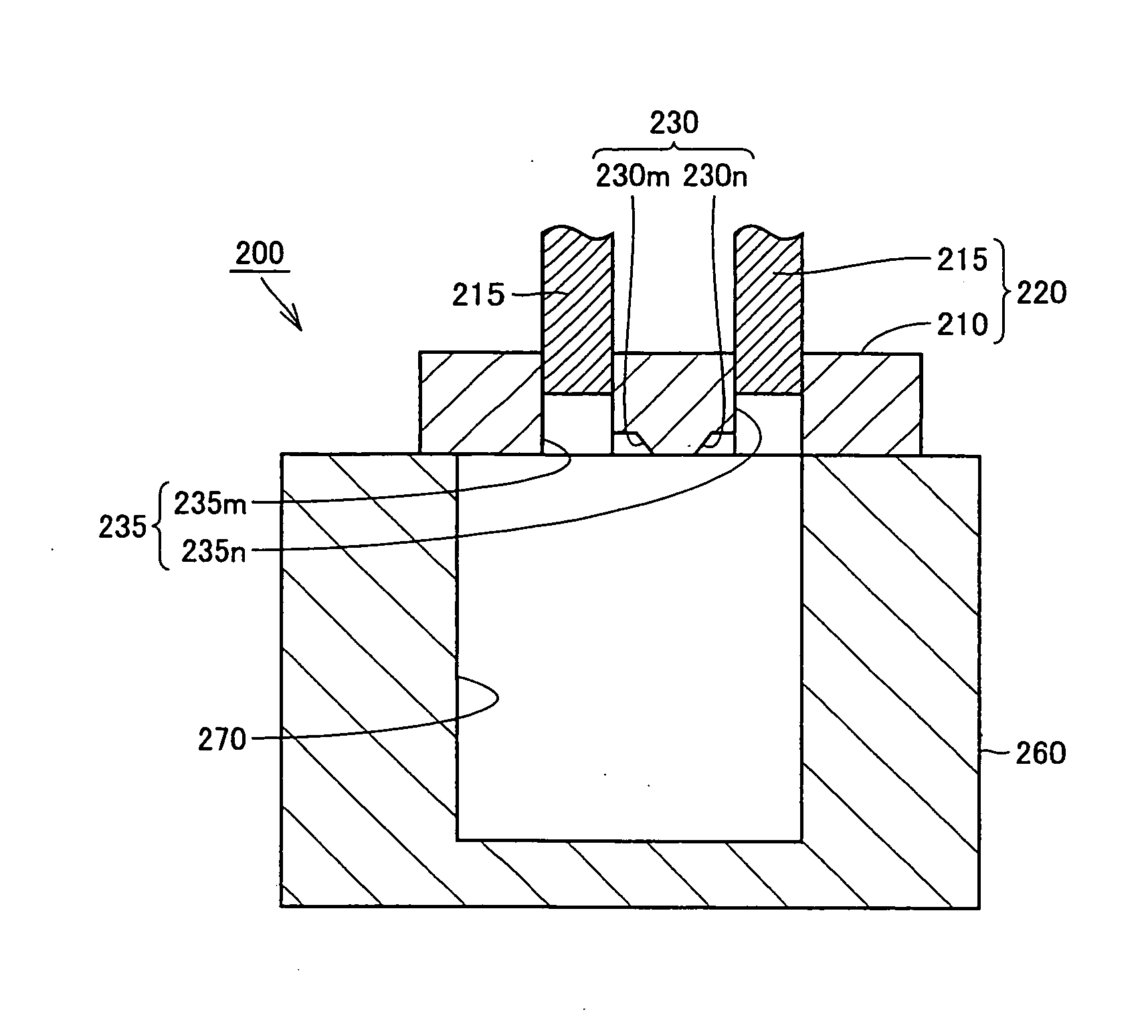
[0079]FIG. 14 is an end view showing an IPM rotor in accordance with Embodiment 2 of the present invention. FIG. 14 corresponds to FIG. 5 of Embodiment 1. IPM rotor 10 of the present embodiment is fabricated using injection apparatus 200 and the method of manufacturing IPM rotor 10 in accordance with Embodiment 1.

[0080]Referring to FIG. 14, in the present embodiment, holding member 26 includes a plurality of injection traces 26g. The plurality of injection traces 26g are formed as thin films on end surface 20a. The plurality of injection traces 26g are formed continuous from holding member 26 filling inner and outer circumferential portions 25p and 25q. The plurality of injection traces 26g are formed at positions overlapping with gates 230m and 230n of FIG. 10. The plurality of injection traces 26g are traces of injection of filler 27 to gap 25 through gates 230m and 230n, in the steps shown in FIGS. 9 and 10 of Embodiment 1.

[0081]IPM rotor 10 in accordance with Embodiment 2 struct...

embodiment 3

[0082]FIGS. 15 and 16 are perspective views showing steps of manufacturing the IPM rotor in accordance with Embodiment 3 of the present invention. The method of manufacturing the IPM rotor in accordance with the present embodiment includes some steps similar to those of the method of manufacturing the IPM rotor in accordance with Embodiment 1. In the following, description of overlapping steps will not be repeated.

[0083]Referring to FIG. 15, in the present embodiment, a plurality of fillers 300 are placed on end surface 20a. Positions where fillers 300 are placed are not limited to those shown in FIG. 15, and the positions may be those shown in FIGS. 11 and 12 of Embodiment 1. Filler 300 is formed by solidifying resin material as the raw material of holding member 26. Filler 300 includes a gate portion 310. Gate portion 310 is formed integrally with filler 300 by the resin material. Each of the plurality of fillers 300 is arranged such that respective gate portions 310 overlap with ...


PUM

PropertyMeasurementUnit
outer circumferenceaaaaaaaaaa
circumferenceaaaaaaaaaa
thermal conductivityaaaaaaaaaa

Abstract

An injection apparatus includes a gate for injecting a filler to a gap between an inner wall of a slot and a permanent magnet. A plurality of gates are provided for one slot. An IPM rotor with improved NV characteristics, and method and apparatus for manufacturing such an IPM rotor can be provided by such a structure.

Description

TECHNICAL FIELD[0001]The present invention generally relates to an IPM (Interior Permanent Magnet) rotor, a method of manufacturing the IPM rotor and an apparatus for manufacturing the IPM rotor. More specifically, the present invention relates to an IPM rotor in which a filler is introduced to a gap between a magnet and an inner wall of a slot for holding the magnet embedded in a core body, as well as to a method of manufacturing the IPM rotor and an apparatus for manufacturing the IPM rotor.BACKGROUND ART[0002]In connection with conventional IPM rotors, Japanese Patent Laying-Open No. 2002-034187, for example, discloses a magnet embedded rotor aimed at attaining higher reliability (Patent Document 1). The magnet embedded rotor includes a laminated core having a plurality of holes formed therein, permanent magnets inserted to respective holes, and resin member introduced to each hole. Patent Document 1 further discloses an injection metal mold used for manufacturing the magnet embe...

Claims


Application Information

Patent Timeline
Patent Type & Authority Applications(United States)
IPC IPC(8): H02K1/27H02K15/03
CPCH02K1/276Y10T29/49012H02K15/03
Inventor MIZUNO, YOTAHATA, HIROSHI
Owner TOYOTA JIDOSHA KK
Why Eureka
Try Eureka