

Driver module structure
A driving module and structure technology, applied in semiconductor/solid-state device manufacturing, electrical components, electric solid-state devices, etc., to achieve high reliability
- Summary
- Abstract
- Description
- Claims
- Application Information
AI Technical Summary
Problems solved by technology
Method used
Image

Examples
no. 1 approach
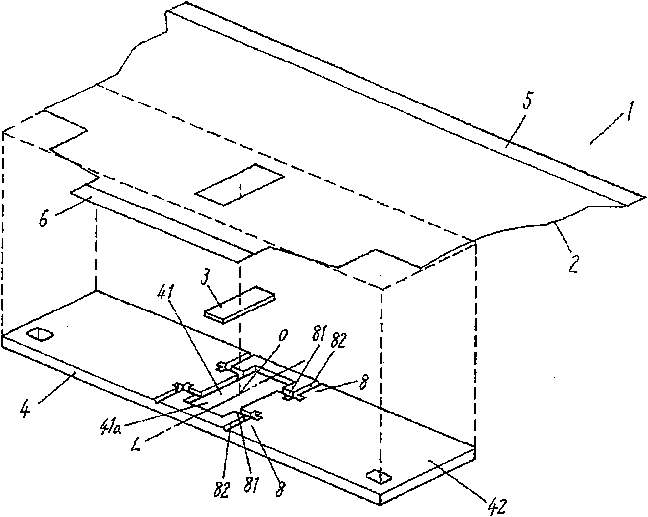
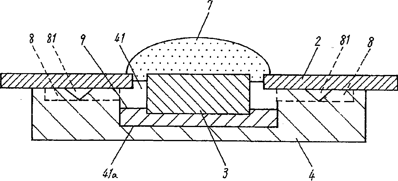
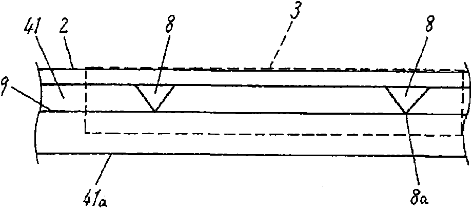
[0045] refer to Figure 1 to Figure 2 , taking a plasma display panel (hereinafter referred to as PDP) driving device as an example, the structure of the driving module according to the first embodiment of the present invention will be described. figure 1 It is an exploded perspective view of a PDP drive device that is an example of the drive module according to the first embodiment of the present invention. figure 2 yes figure 1 Cross-sectional view of the PDP drive unit. image 3 It is a figure of the inner peripheral wall of the recessed part of a radiator seen from the inside.
[0046] Such as figure 1 and figure 2 As shown, the PDP drive device 1 has a flexible substrate 2 , a semiconductor device 3 assembled on the flexible substrate 2 , and a radiator 4 mounted on the flexible substrate 2 .
[0047] The flexible substrate 2 is formed of a flexible plastic film, has an electrode 5 connected to the PDP at one end, and an electrode 6 connected to a control substrate...
no. 2 approach
[0067] The following reference Figure 4 A PDP drive device according to a second embodiment of the present invention will be described. Figure 4 It is a perspective view of a PDP drive device which is an example of the drive module according to the second embodiment of the present invention. also, Figure 4 in, with figure 1 The same structure is marked with the same symbol, and the explanation is omitted.
[0068] In the PDP drive device 1x according to the second embodiment, grooves 8x functioning as air passages formed in the radiator 4x are respectively formed in the center of the two long sides of the rectangular concave portion 41 . The groove 8x is preferably substantially V-shaped in cross section, similarly to the groove 8 described in the radiator 4 according to the first embodiment.
[0069] In the radiator 4x formed with such grooves 8x, even if grease infiltrates into one of the grooves 8x, the other groove 8x at a position opposite to the one groove 8x can ...
no. 3 approach
[0071] The following reference Figure 5 A PDP drive device according to a third embodiment of the present invention will be described. Figure 5 It is a perspective view of a PDP drive device which is an example of the drive module according to the third embodiment of the present invention. also, Figure 5 in, with figure 1 The same symbols are attached to the same structures, and the description thereof will be omitted.
[0072] In the PDP drive device 1y according to the third embodiment, the grooves 8y functioning as air passages formed in the radiator 4y are formed in four directions from the four corners of the concave portion 41 formed in a rectangular shape with the concave portion 41 as the center. extend. Even if the groove 8y is formed in the radiator 4y in this way, the same effect as that of the first embodiment can be obtained.
[0073] By forming the grooves 8y to extend in four directions from the four corners of the recess 41 around the recess 41, the bon...
PUM
 Abstract
Description
Claims
Application Information