Deployable passive broadband aircraft tracking

a broadband and aircraft tracking technology, applied in the direction of aircraft traffic control, direction finders, instruments, etc., can solve the problems of significant pressure on the performance improvement of atc systems and surveillance technologies, reduce separation and flexible route planning, and reduce the cost of retrofitting existing aircraft, including certification costs and the opportunity cost of the associated operational downtim

Inactive Publication Date: 2010-08-17
ERA AS
View PDF662 Cites 15 Cited by
  • Summary
  • Abstract
  • Description
  • Claims
  • Application Information

AI Technical Summary

Problems solved by technology

In turn, this will require reduced separation and flexible route planning, which will place significant pressure on improved performance from ATC systems and surveillance technologies.
Firstly, ADS-B requires new equipment on-board each aircraft and, while incremental costs of ADS-B equipage for new aircraft is small, the costs to retrofit existing aircraft, including certification costs and the opportunity costs of the associated operational downtime, are significant.
Secondly, the transition from radar to ADS-B will need to address issues of data integrity and validation before ANSP's can undertake safety-critical separation services using position information derived no longer from their own radar infrastructure but from information provided directly from the aircraft avionics.
It seems likely that, even if the safety case supports ADS-B-only surveillance, issues of governance and responsibility will require ANSP's to establish an independent means of backup and validation for ADS-B and the associated business case will be significantly impacted if this backup system must rely only on ongoing use of radar infrastructure.
Encrypting ADS-B has been proposed as a means to validate ADS-B, but this technique does not support backup surveillance.
Thirdly, surveillance based on the broadcast of self-reported aircraft position raises security issues, both in terms of the ease with which aircraft can be tracked from the ground by almost anyone, using low-cost and readily available ADS-B decoding units, and also by the potential for an aircraft to knowingly mislead a surveillance system by spoofing its position information and appearing to be in a position other than the position at which it is actually located.
Long range of detection (radio horizon is main limitation)

Method used


Image

  • Deployable passive broadband aircraft tracking
  • Deployable passive broadband aircraft tracking
  • Deployable passive broadband aircraft tracking

Examples


first embodiment

[0085]FIG. 9 is block diagram illustrating the present invention, providing integrated tracking using passive broadband. As illustrated in the embodiment of FIG. 9, the invention takes the system for deployable passive broadband detection and extends it by incorporating the capability to decode position for ADS-B, SSR multilateration, and broadband multilateration. In this embodiment, aircraft 100 transmits a signal, which is received at a minimum of three stations 140, 140, and 150. Antenna 150 may receive ADS-B signals and generate an ADS-B position signal as generated by aircraft 100. Antennas 140 may receive other signals but may not necessarily generate ADS-B position data. Signals 110, 120 may include all pulse and high bandwidth signals emanating from aircraft 100 including, but not limited to, UAT, DME, TACAN, SSR, Mode S, ADS-B, Pulse Radar, Weather Radar, Communications, and Military Radar.

[0086]In the embodiment of FIG. 9, it is assumed that ADS-B is transmitted by the ai...

second embodiment

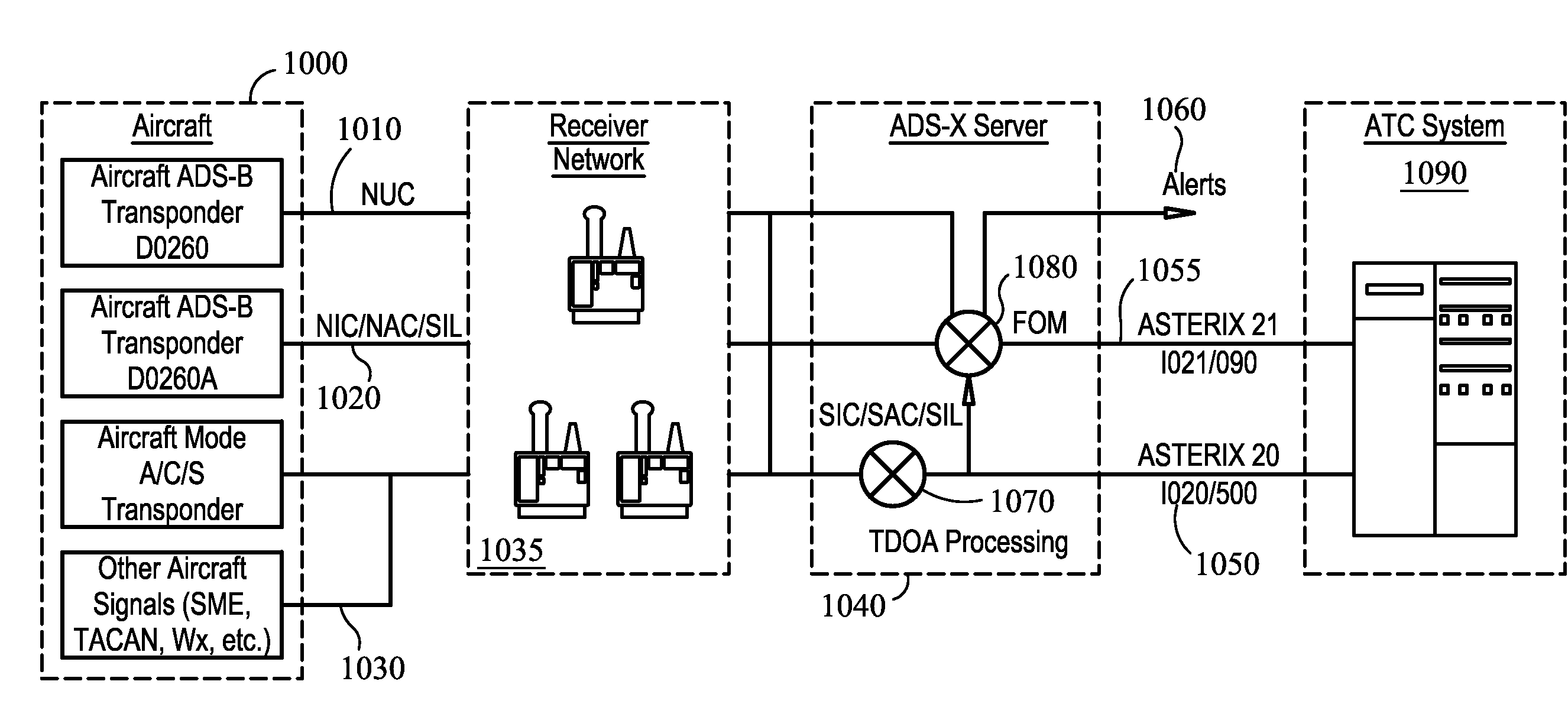
[0092]FIG. 10 is a block diagram illustrating the present invention, providing validation of a self-reported position. In this embodiment of the present invention takes the system for deployable passive broadband detection and extends it by incorporating the capability to decode self-reported position for ADS-B, and compare it to line of calculated position, or line of precision, derived from multilateration techniques applied to various signals received from the aircraft.

[0093]Referring to FIG. 10, aircraft 1000 emits an ADS-B position report 1010 along with associated quality and integrity information (NIC / NAC / SIL) 1020, as well transponder and other aircraft signals 1030. These signals 1010, 1020, and 1030 are received at one or more of the stations 1035 and is decoded and made available for onward processing to the ATC system 1090.

[0094]Simultaneously, the same signal, and / or other signals emitted by the aircraft 1010, 1020, and 1030, are received at a number of stations and a p...

third embodiment

[0097]FIG. 11 is a block diagram of the present invention, which shows a passive ranging and passive Angle of Arrival ground-based surveillance system and vehicle-based surveillance system that provides the capabilities to decode self-reported ADS-B position, determine independent surveillance position of an ADS-B target using passive ranging and passive Angle of Arrival measurement techniques, and validate self-reported ADS-B position using the independent surveillance position.

[0098]As shown in the third embodiment illustrated in FIG. 11, the aircraft [340] broadcasts an ADS-B report signal [350] that is received by another airborne aircraft [330] and ground based direction finding antennas [360]. The receivers [365] decode and measure the Angle of Arrival and Time of Arrival of the ADS-B report signal [350]. The Angle of Arrival, Time of Arrival, decoded data, including altitude and identification, are sent by the receiver [365] to the surveillance processor [300]. The surveillan...


PUM


Abstract

In a first, preferred embodiment of the present invention, integrated tracking is provided using passive broadband. The invention takes the system for deployable passive broadband detection and extends it by incorporating the capability to decode position for ADS-B, SSR multilateration, and broadband multilateration. In a second embodiment, validation of a self-reported position is provided. The invention takes the system for deployable passive broadband detection and extends it by incorporating the capability to decode self-reported position for ADS-B, and compare it to line of calculated position, or line of precision, derived from multilateration techniques applied to various signals received from the aircraft. In a third embodiment, validation of a self-reported ADS-B position using independent surveillance is provided by the system.

Description

CROSS-REFERENCE TO RELATED APPLICATIONS[0001]This application is a Continuation-In-Part of U.S. patent application Ser. No. 11 / 492,711, filed Jul. 25, 2006, and incorporated herein by reference; This application is a Continuation-In-Part of U.S. patent application Ser. No. 11 / 429,926, filed on May 8, 2006, and incorporated herein by reference; This application is a Continuation-In-Part of U.S. patent application Ser. No. 11 / 343,079, filed on Jan. 30, 2006, and incorporated herein by reference; This application is also a Continuation-In-Part of U.S. patent application Ser. No. 11 / 342,289 filed Jan. 28, 2006 and incorporated herein by reference; This application is a Continuation-In-Part of U.S. patent application Ser. No. 11 / 209,030, filed on Aug. 22, 2005, and incorporated herein by reference; This application is a Continuation-In-Part of U.S. patent application Ser. No. 11 / 257,416, filed on Oct. 24, 2005, and incorporated herein by reference; This application is a Continuation-In-P...

Claims


Application Information

Patent Timeline
Patent Type & Authority Patents(United States)
IPC IPC(8): G01S3/02G01S5/02
CPCG01S5/0027G01S5/0221G01S5/04G01S5/06G01S7/003G08G5/0026G08G5/0082G01S5/02213
Inventor SMITH, ALEXANDER E.HULSTROM, RUSSELLEVERS, CARL A.
Owner ERA AS
Why Eureka
Try Eureka