
Display source

a technology of display source and display device, which is applied in the direction of cathode-ray tube indicators, optics, instruments, etc., can solve the problems of incongruity related drop of transmitting digital display device b>2/b>, and achieve the effect of reducing resolution and cos

Inactive Publication Date: 2010-08-17
BAE SYSTEMS PLC
View PDF8 Cites 93 Cited by
  • Summary
  • Abstract
  • Description
  • Claims
  • Application Information

AI Technical Summary

Benefits of technology

[0020]In this manner, should it be necessary to replace the image generator of the display source with a different type of image generator, then it will only be necessary to redesign the arrangement of the display source, rather than the primary relay optical arrangement of the helmet mounted display or head mounted display. It will be understood that redesigning the primary relay optical arrangement of the helmet mounted display or head mounted display will incur a relatively large cost when compared to redesigning the display source, especially when one considers the speed at which advances are made in the development of image generators and that such devices can quickly become superseded. The primary relay optical arrangement for a helmet mounted display or head mounted display will have a fixed focal length and any change in size of the image generator will impact the optical performance of the primary relay optical arrangement. That is, if there is an increase in size of the image generator, then display pixels of the image generator will exist outside of the usable area as constrained by the primary relay optical arrangement, which will result in a lower resolution as observed by a viewer using the helmet mounted display or head mounted display. Conversely, if the image generator is reduced in size, then the constrains of the primary relay optical arrangement will result in a lost of field of view as observed by a viewer using the helmet mounted display or head mounted display. A redesign of the display source relay optical arrangement is cheaper and can be implemented so as to provide a correctly sized image to the primary relay optical arrangement of the helmet mounted display or head mounted display.

Problems solved by technology

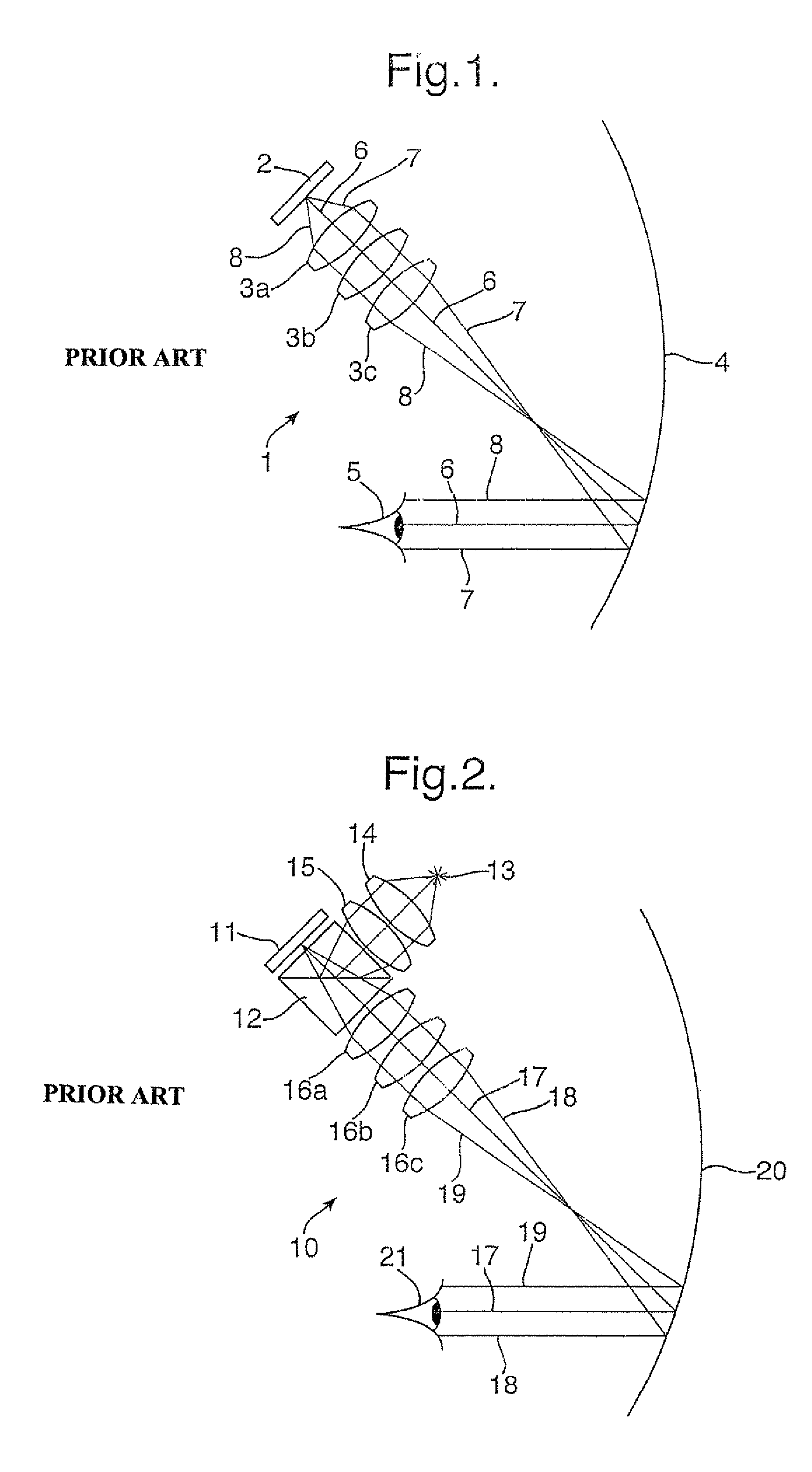
The problem with this approach is that transmissive digital display devices 2 have an inherent drop in contrast related to the angle of incidence between the transmissive digital display device 2 and the primary relay optical elements 3a to 3c.

Method used


Image

  • Display source
  • Display source
  • Display source

Examples


Embodiment Construction

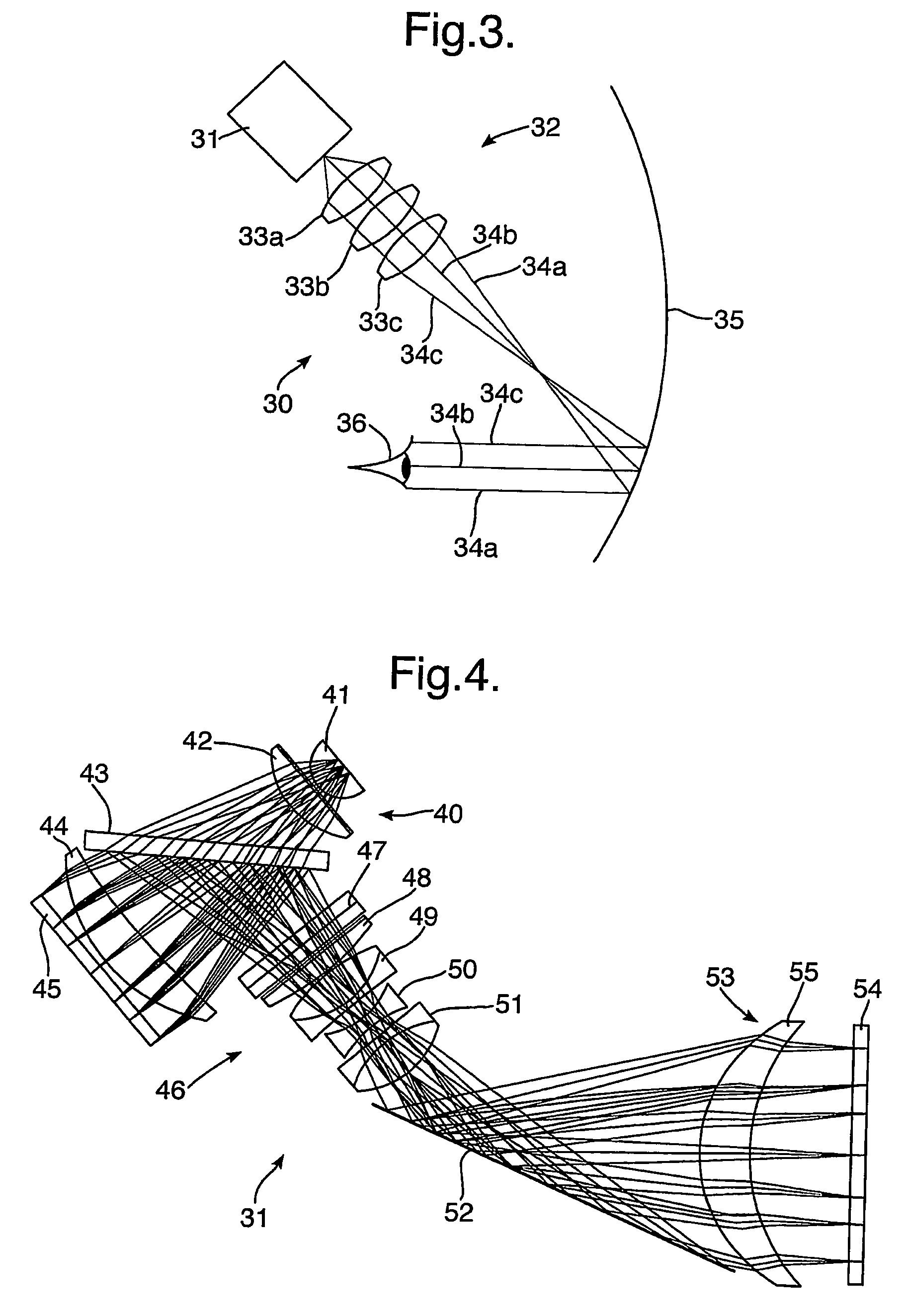
[0026]This invention provides a different philosophy to that of the prior art described with reference to FIGS. 1 and 2. In general, a primary relay optical arrangement of a helmet mounted display or a head mounted display is very complex and an expensive item to produce. If the primary relay optical arrangement were arranged to directly image a digital display device, then the primary relay optical arrangement would need to be a bespoke design suited to the specific digital display device utilised in the helmet mounted display or head mounted display. Any change in the mechanical or optical properties of the digital display device could render the entire helmet mounted display or head mounted display system obsolete. Therefore, a display source is employed in the invention to be directly imaged by the primary relay optical arrangement and that can be redesigned relatively simply and cheaply if the digital display device for the helmet mounted display or head mounted display needs t...


PUM


Abstract

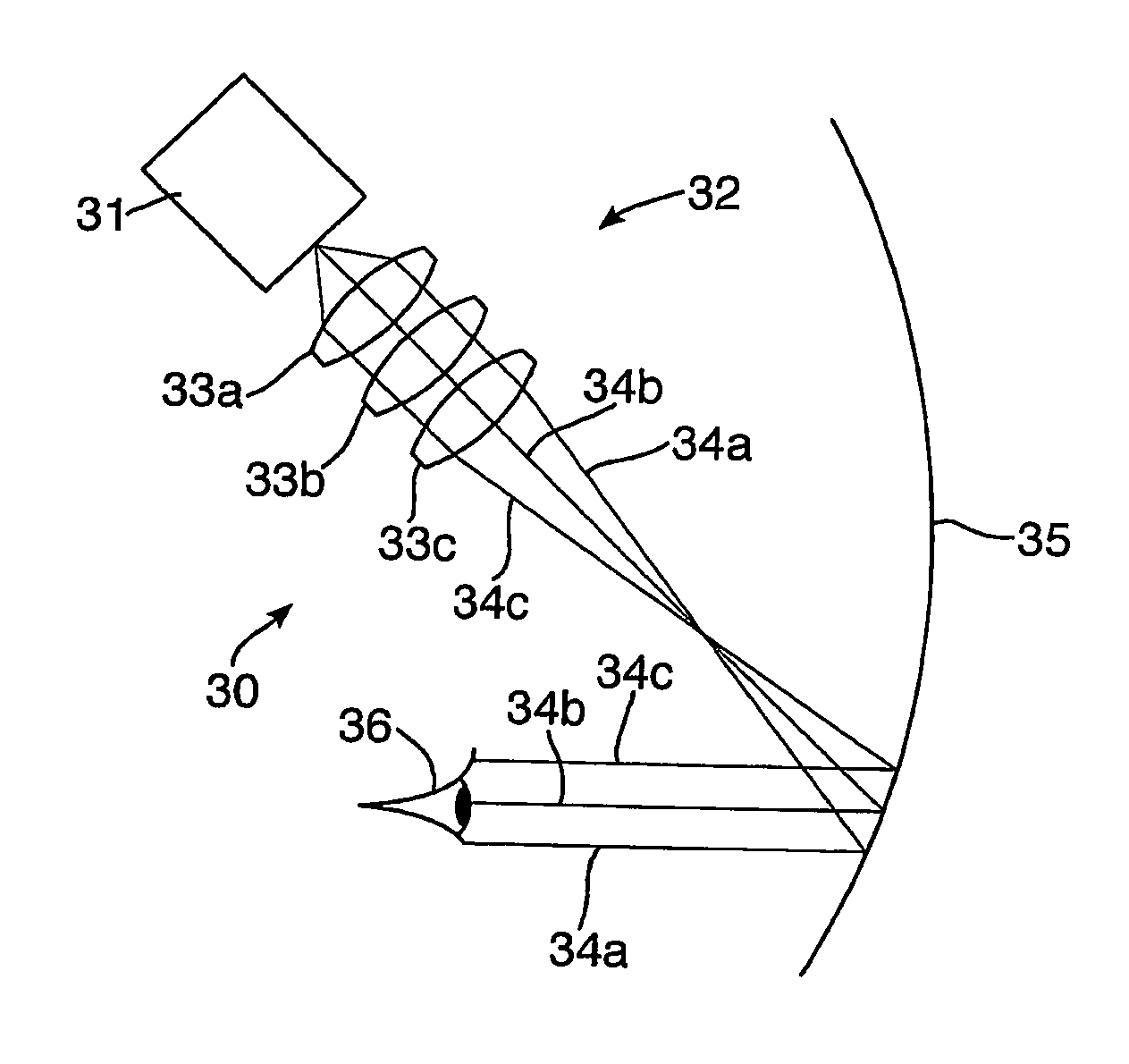
A helmet mounted display 30 includes a display source 31 arranged to be directly imaged by a primary relay optical arrangement 32 having relay optical elements 33A, 33B and 33C. Light exiting the primary relay optical arrangement 32 indicated by ray traces 34A, 34B and 34C continue towards a visor 35 which is arranged to reflect incident light to a exit pupil located in a convenient position for a viewer 36. The display source 31 includes a light source, beam splitter, reflective liquid crystal display and a display source relay optical arrangement to provide an output image at an output diffuser screen. The image at the output screen is then directly imaged by the primary relay optical arrangement 32. Should the reflective liquid crystal display require modification or replacement with a newer model, then the display source 31 can be redesigned to accommodate the new reflective liquid crystal display rather than re-engineering the primary relay optical arrangement 32 at greater expense.

Description

BACKGROUND OF THE INVENTION[0001](1) Field of the Invention[0002]This invention relates to a display source which is particularly, but not exclusively, suitable for use in a helmet mounted display or head mounted display.[0003](2) Description of Related Art[0004]Traditional, as illustrated in FIG. 1, a prior art helmet mounted display 1 can be constructed to directly image a transmissive digital display device 2 using only primary relay optical elements 3a, 3b and 3c to transmit light generated by the digital display device 2 onto a visor 4, which is arranged to reflect light back to an exit pupil at the point of a viewer 5. It will be understood that the viewer 5 observes a forward scene through the visor 4 and the image produced by the digital display device 2 is superimposed upon the forward scene. The problem with this approach is that transmissive digital display devices 2 have an inherent drop in contrast related to the angle of incidence between the transmissive digital displ...

Claims


Application Information

Patent Timeline
IPC IPC(8): G02F1/1335G02B27/14G09G5/00
CPCG02B27/0172G02B5/30G02B2027/0118G02B2027/0123
Inventor SIMMONDS, MICHAEL DAVID
Owner BAE SYSTEMS PLC
Learn More