Means and apparatus for control of remote electronic devices

a technology for electronic devices and means, applied in the direction of program control, wireless commuication services, instruments, etc., can solve the problem that the standard cellular phone cannot be called using the min's assigned to the central location, and achieve the effect of improving or solving the problems and deficiencies of the ar

Inactive Publication Date: 2010-08-17
MUSCO
View PDF40 Cites 68 Cited by
  • Summary
  • Abstract
  • Description
  • Claims
  • Application Information

AI Technical Summary

Benefits of technology

[0025]A principal object of the present invention is therefore to provide an apparatus and method of controlling remotely located devices, which improves over or solves the problems and deficiencies in the art.

Problems solved by technology

Therefore, a standard cellular phone cannot be called using the MIN's assigned to the central location.

Method used


Image

  • Means and apparatus for control of remote electronic devices
  • Means and apparatus for control of remote electronic devices
  • Means and apparatus for control of remote electronic devices

Examples


Embodiment Construction

[0078]To assist in a better understanding of the invention, a detailed description of a preferred embodiment will now then be set forth. It is to be understood that this describes but one specific form of the invention can take, and that others are possible. Appended drawings will be referred to as description.

[0079]A brief overview of the preferred embodiment in the particular environment for this example of the invention will be given. A specific description of the structure or physical components of the preferred embodiment will follow. Thereafter, a discussion of how the structure functions in its working environment will be set forth. Finally, operational matters and features, as well as alternative embodiments, will be discussed.

[0080]Overview

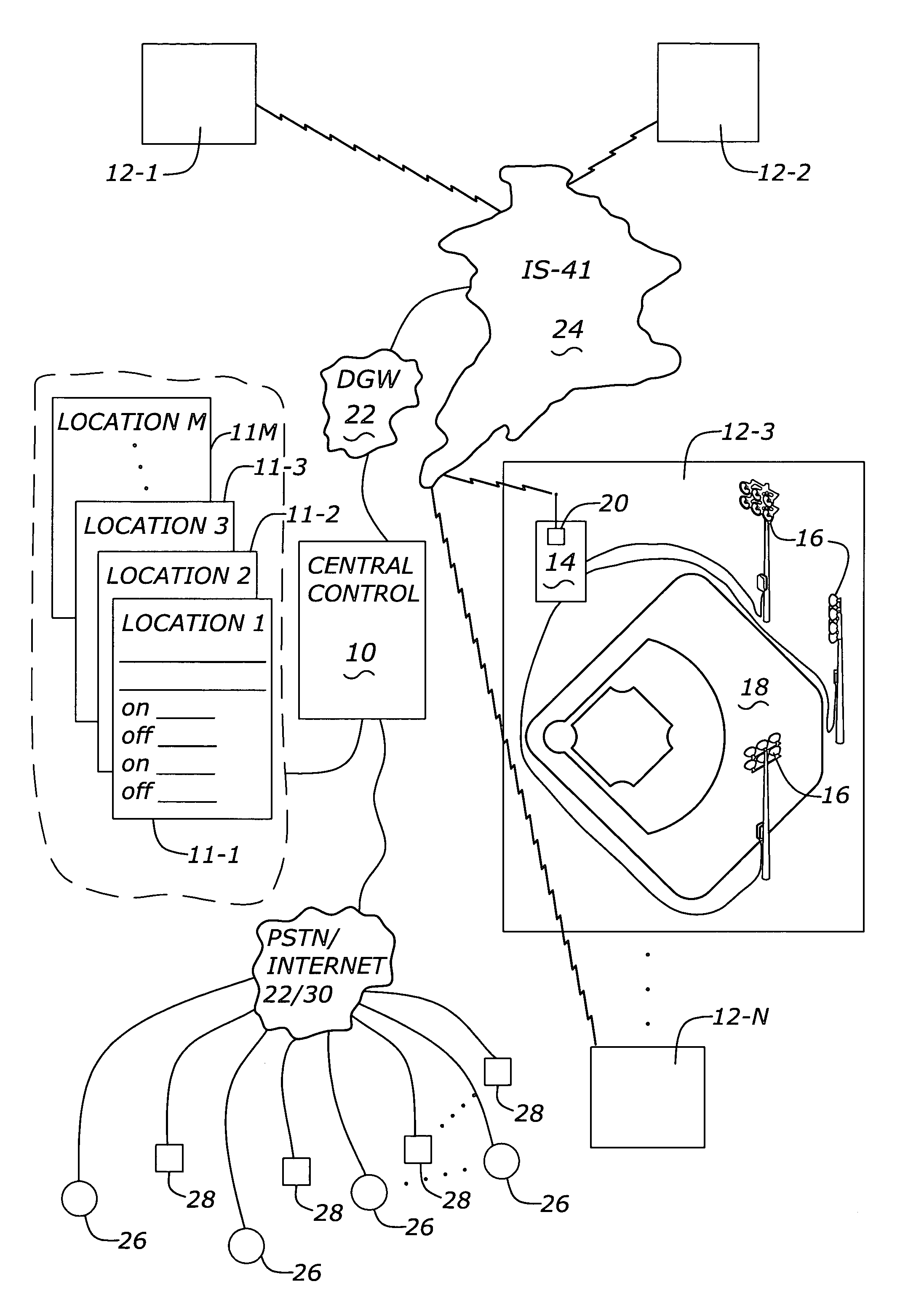
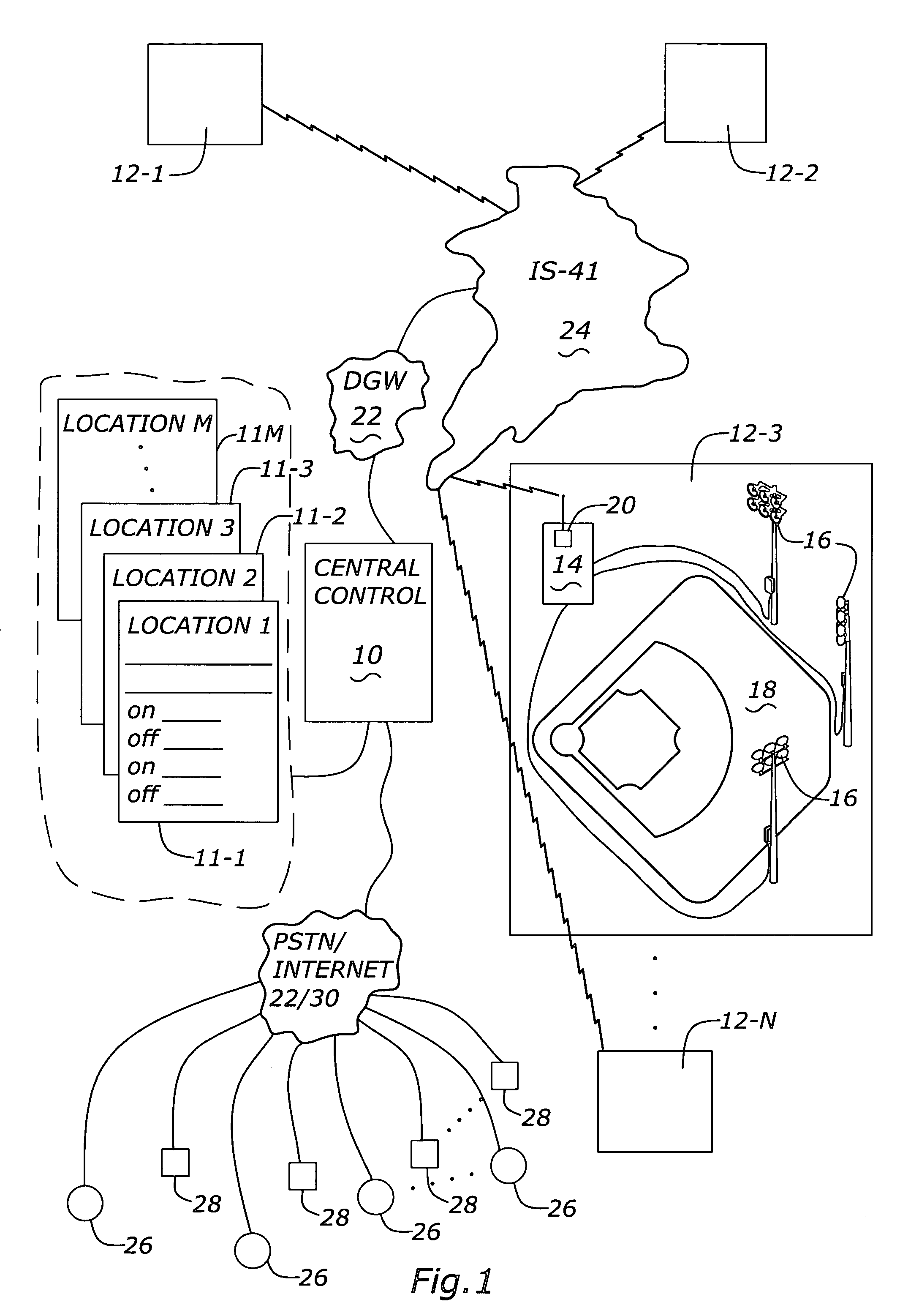
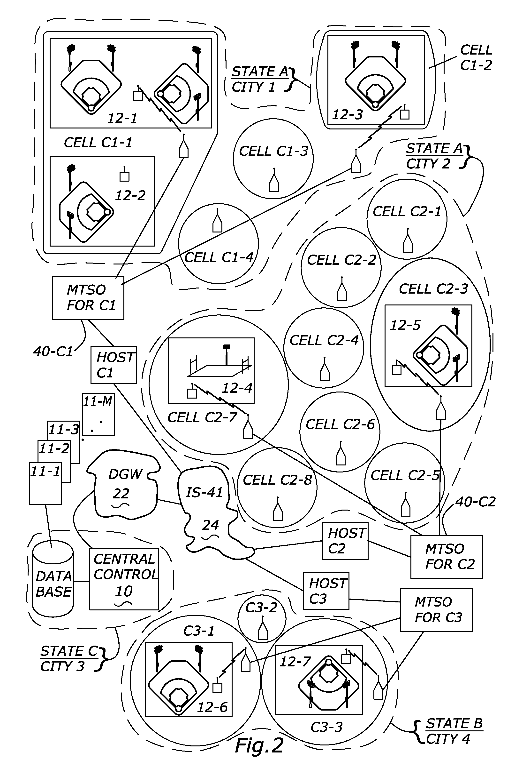
[0081]This embodiment will be discussed in the context of remotely controlling lighting systems at a number of remote locations. However, it is to be understood that the invention can be applied in a variety of ways to a variety of remote...


PUM


Abstract

An apparatus to control remote devices or equipment via existing cellular telephone networks. The apparatus receives information from a customer concerning a specific function, which the customer wants to perform at the remote equipment. A Central Control receives this information from the customer and correlates the function to a specific cellular telephone MIN number, which has been pre-programmed in a computer at the Central Control. The MIN number is then sent to a cellular provider. The cellular provider then transmits the MIN number to an antenna, which transmits the MIN number to a remote equipment controller at the remotely located equipment. The remote equipment controller then takes the a part of the MIN and gives these numbers to a PLC at the remote equipment controller. The PLC then memory maps the part of the MIN to a specific function to be carried out by the remote equipment controller. Then the remote equipment controller carriers out specified functions at the remote equipment.

Description

CROSS-REFERENCE TO RELATED APPLICATIONS[0001]This application claims the benefit of U.S. Provisional Application(s) Nos. 60 / 142,109 filed Jul. 2, 1999.BACKGROUND OF THE INVENTION[0002]1. Field of the Invention[0003]The present invention relates to control of remote devices, and in particular, control of remotely located electrical equipment, including but not limited to, lighting systems.[0004]2. Problems in the Art[0005]Large area lighting systems are well known in the art. They can take many different forms. From baseball diamonds to playgrounds, to parking lots, to golf courses; large area lighting systems are all around in today's society.[0006]In some instances, the lighting system is turned on and off automatically by timers, photo detectors, or other devices. This works reasonably well if the lights are used on a regular schedule or according to regularly repeating occurrences. In other cases, employees, staff members, or other persons must be hired or have the obligation to ...

Claims


Application Information

Patent Timeline
Patent Type & Authority Patents(United States)
IPC IPC(8): H04W4/00B60Q1/124G07G1/14H04M3/00H04M11/00H04M11/04H04Q1/00
CPCH04M11/04H04M11/002H05B47/19
Inventor CROOKHAM, JOE P.RIVERA, ANTONIOFOSTER, MICHAEL B.MARSH, RYAN A.TIPPETT, WALTER R.COOLEY, PATRICK K.
Owner MUSCO
Why Eureka
Try Eureka