Vacuum cleaner

a vacuum cleaner and vacuum cleaner technology, applied in the field of vacuum cleaners, can solve the problems of difficult cleaning of dust collecting boxes, difficult dismounting of filters from the inside of the vacuum cleaner, and requiring a lot of tim

Inactive Publication Date: 2010-08-24
LG ELECTRONICS INC
View PDF31 Cites 80 Cited by
  • Summary
  • Abstract
  • Description
  • Claims
  • Application Information

AI Technical Summary

Benefits of technology

[0016]An object of the present invention is to provide a vacuum cleaner having a dust collector assembly which is easy to replace and clean.
[0026]In another aspect of the present invention, a vacuum cleaner includes suction means provided to an inside of a body of the vacuum cleaner for providing suction force, a suction nozzle for drawing room air by the suction force provided from the suction means, a dust collecting box for cleaning, and discharging the room air drawn through the suction nozzle, the dust collecting box having an opening in an upper surface thereof, a filter assembly including an upper holding part selectively fastened to an upper surface of an edge of the opening, the upper holding part having an air discharge hole at a central portion thereof, a lower holding part spaced a distance downward from the upper holding part, and a cylindrical filter between the upper holding part and the lower holding part, the filter having a discharge passage therein, and a lower cover mounted to be rotatable around a cover hinge provided to a lower portion of the dust collecting box for opening / closing the lower portion of the dust collecting box selectively, a separation plate mounted to divide an inside space of the dust collecting box into an upper space and a lower space, the separation plate having a hole at one side thereof, and a partition plate between the separation plate and the lower cover, for prevention of circulation of the air drawn thereto.
[0028]In further aspect of the present invention, a vacuum cleaner includes suction means provided to an inside of a body of the vacuum cleaner for providing suction force, a suction nozzle for drawing room air by the suction force provided from the suction means, a dust collecting box for cleaning, and discharging the room air drawn through the suction nozzle, the dust collecting box having an opening in an upper surface thereof, a filter assembly fastened to an edge of the opening selectively, for filtering dust from drawn air, and discharging upward, a lower cover mounted to be rotatable around a cover hinge provided to a lower portion of the dust collecting box, a separation plate mounted over, and as one unit with the lower cover to divide an inside space of the dust collecting box into an upper space and a lower space, the separation plate having a diameter smaller than an inside diameter of the dust collecting box, and a partition plate between the separation plate and the lower cover, for prevention of circulation of the air drawn thereto.

Problems solved by technology

First, the related art vacuum cleaner has a structure of the dust collecting box difficult to clean, to require much time, or to have inconvenience in cleaning the dust collecting box after finish of the operation.
Second, dismounting of the filter from an inside of the vacuum cleaner is not easy, to cause difficulty in replacement and cleaning of the filter.

Method used


Image

  • Vacuum cleaner
  • Vacuum cleaner
  • Vacuum cleaner

Examples


Embodiment Construction

[0039]Reference will now be made in detail to the preferred embodiments of the present invention, examples of which are illustrated in the accompanying drawings. Wherever possible, the same reference numbers will be used throughout the drawings to refer to the same or like parts.

[0040]A vacuum cleaner in accordance with each of the embodiments of the present invention will be described with reference to FIGS. 2˜8.

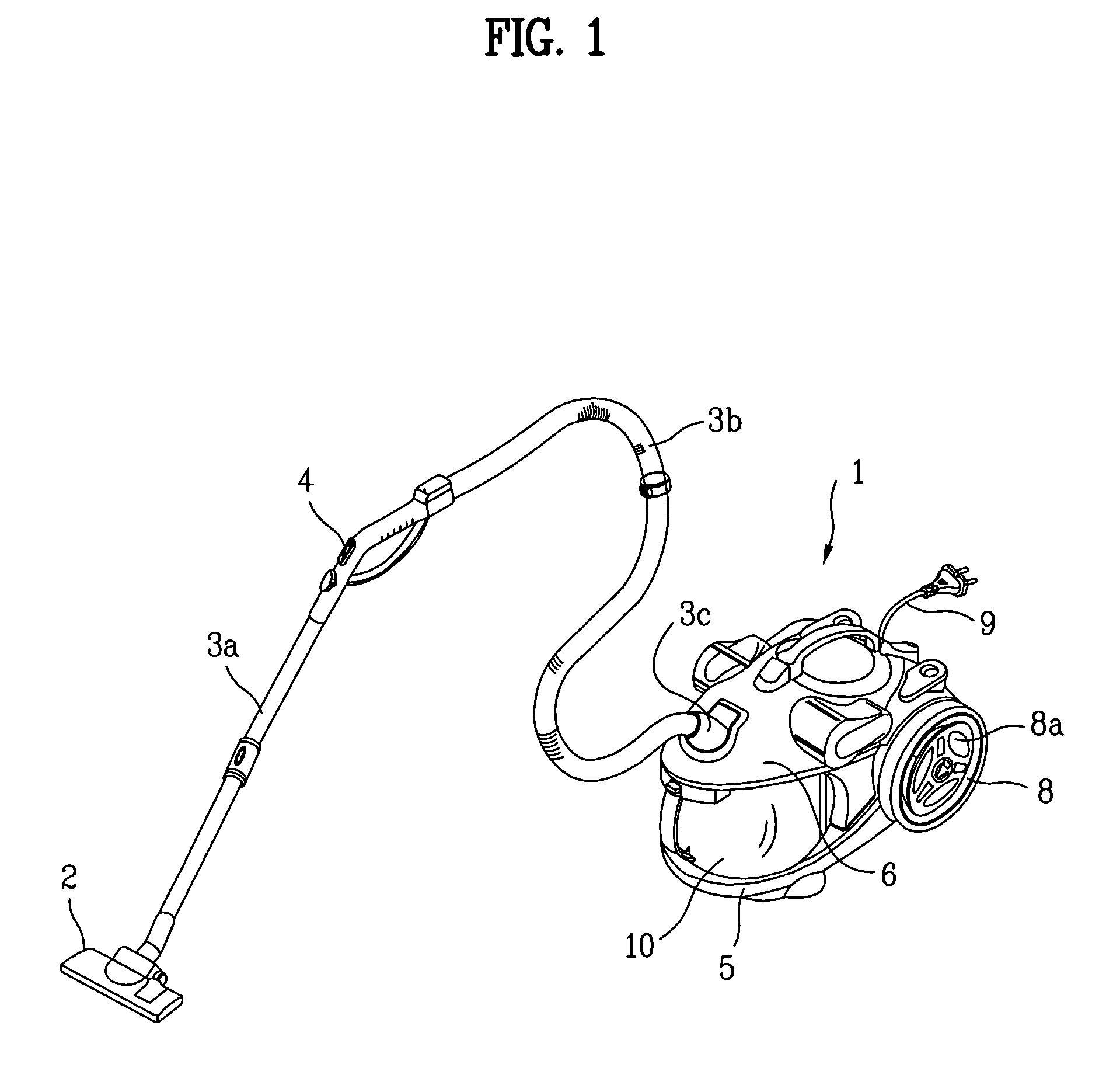
[0041]In the vacuum cleaners, there are canister type and upright type of vacuum cleaners. The canister type of vacuum cleaner has a suction nozzle and a body provided separately and connected with a connection tube. Opposite to this, the upright type of vacuum cleaner has the suction nozzle and the body provided as one unit.

[0042]The following embodiments are applicable all types of vacuum cleaners including the canister type and the upright type of vacuum cleaners.

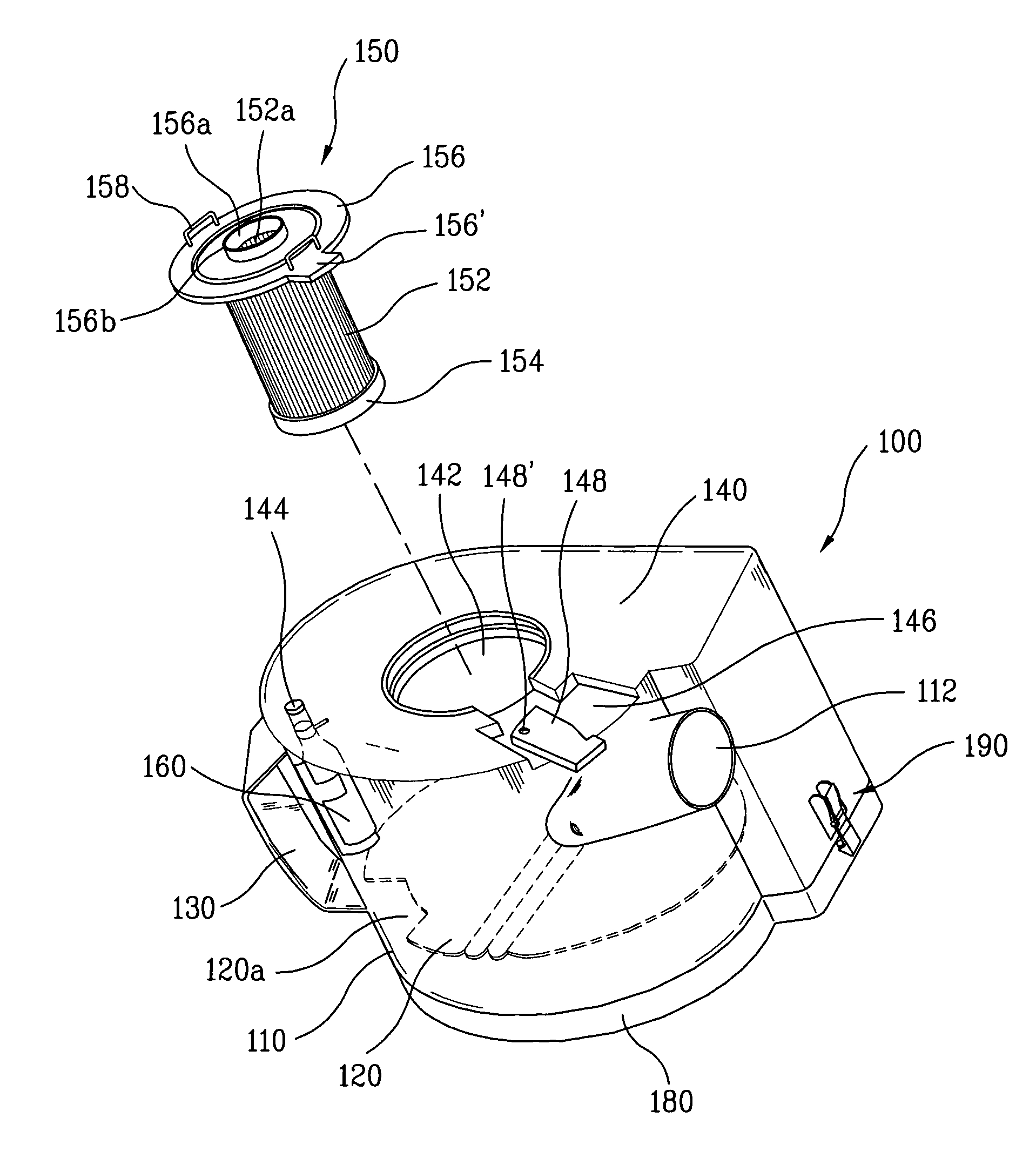
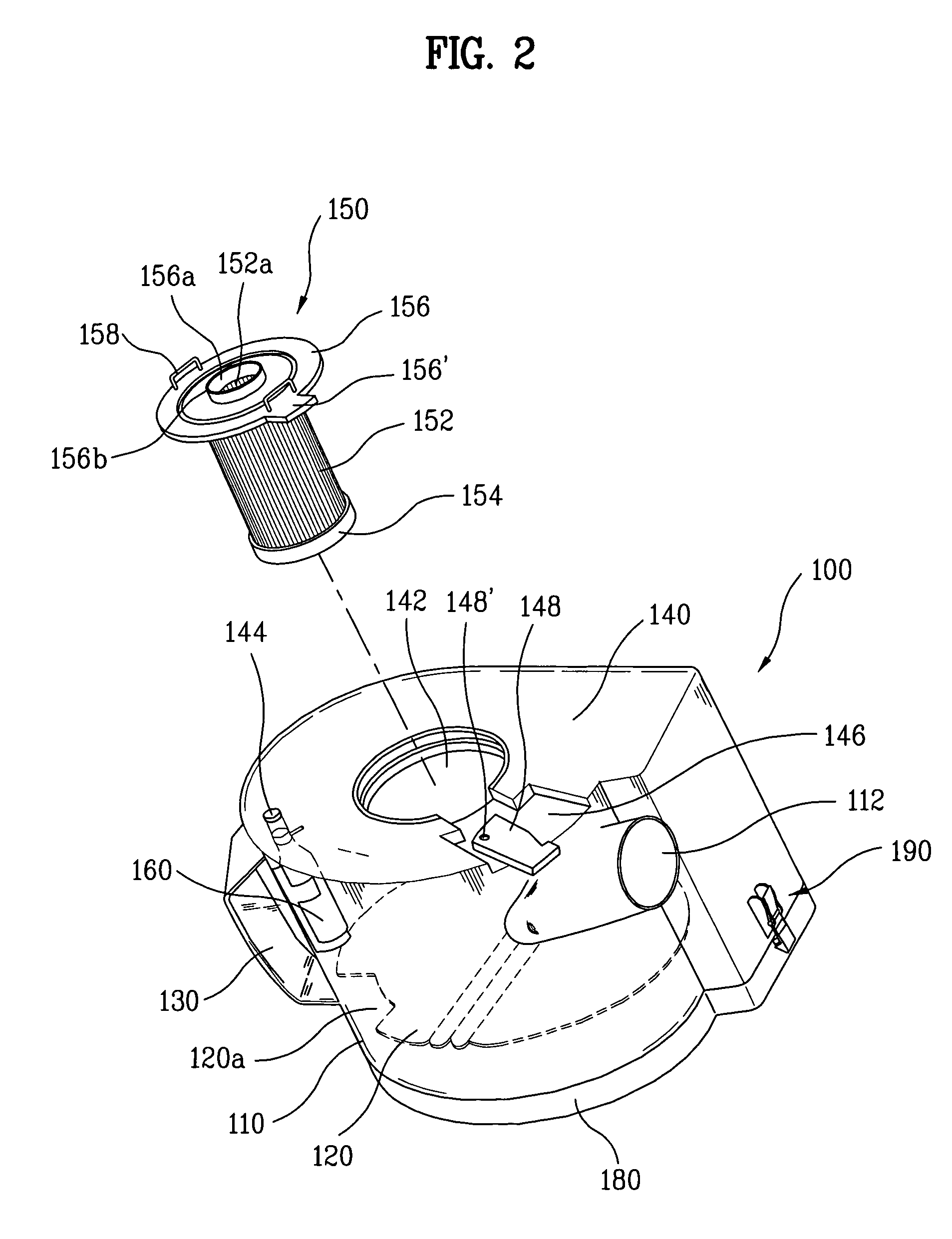
[0043]FIG. 2 illustrates a disassembled perspective view of a dust collector assembly in a vacuum cleaner in ...


PUM


Abstract

A vacuum cleaner is provided that including suction device that provides suction force, a suction nozzle that draws air by the suction force provided from the suction device, a dust collecting box that cleans and discharges the air drawn through the suction nozzle, the dust collecting box having an opening in an upper surface thereof, a filter assembly including an upper holding part selectively fastened to an edge of the opening, the upper holding part having an air discharge hole at a central portion thereof, a lower holding part spaced a distance downward from the upper holding part, and a filter between the upper holding part and the lower holding part that filters dust from air, the filter having a discharge passage therein, and a lower cover that selectively opens / closes a lower portion of the dust collecting box. This structure permits easy cleaning and replacement of the dust collector assembly in a vacuum cleaner.

Description

CROSS-REFERENCE TO RELATED APPLICATIONS[0001]This application claims the benefit of Korean Application Nos. P2004-16479, P2004-16480, and P2004-16482, three of which were filed on Mar. 11, 2004, and are hereby incorporated by reference as if fully set forth herein.BACKGROUND OF THE INVENTION[0002]1. Field of the Invention[0003]The present invention relates to vacuum cleaners, and more particularly, to a vacuum cleaner having an improved dust collector assembly.[0004]2. Description of the Related Art[0005]In general, the vacuum cleaner draws dust-laden air from a floor of a room, removes the dust from the air, and discharges only the air again.[0006]FIG. 1 illustrates a perspective view of a related art vacuum cleaner. As shown, the vacuum cleaner is provided with a body 1, and a suction nozzle 2.[0007]The body 1 has a suction means mounted therein for drawing room air. Air is drawn from the floor to the body 1 through the suction nozzle 1 by a suction force generated at the body 1.[...

Claims


Application Information

Patent Timeline
Patent Type & Authority Patents(United States)
IPC IPC(8): A47L9/10A47L9/16
CPCA47L9/106A47L9/127A47L9/1683
Inventor KANG, SUNG SUJUNG, JAE DUCK
Owner LG ELECTRONICS INC
Why Eureka
Try Eureka