Engine-driven work machine resiliently supported on a frame

a work machine and frame technology, applied in the direction of machines/engines, mechanical equipment, combustion air/fuel air treatment, etc., can solve the problems of considerable operational noise the operational noise of the cooling fan is leaked from the inlet of the cooling-air passage, so as to prevent the sound from leaking from the ventilation gap

Inactive Publication Date: 2010-08-24
HONDA MOTOR CO LTD
View PDF6 Cites 28 Cited by
  • Summary
  • Abstract
  • Description
  • Claims
  • Application Information

AI Technical Summary

Benefits of technology

[0009]Accordingly, it is an aspect of the present invention to provide an engine-driven work machine, wherein leakage of operational noise from an inlet of a cooling-air passage is prevented to provide the engine-driven work machine with a relatively high silencing performance.

Problems solved by technology

However, in the disclosed generator, a considerable amount of the operational noise is leaked from the inlet of the cooling-air passage.
Particularly, because the cooling fan is disposed on the inlet side of the cooling-air passage, a considerable amount of operational noise from the cooling fan is leaked from the inlet of the cooling-air passage.

Method used


Image

  • Engine-driven work machine resiliently supported on a frame
  • Engine-driven work machine resiliently supported on a frame
  • Engine-driven work machine resiliently supported on a frame

Examples


second embodiment

[0115]the present invention shown in FIG. 22 will now be described.

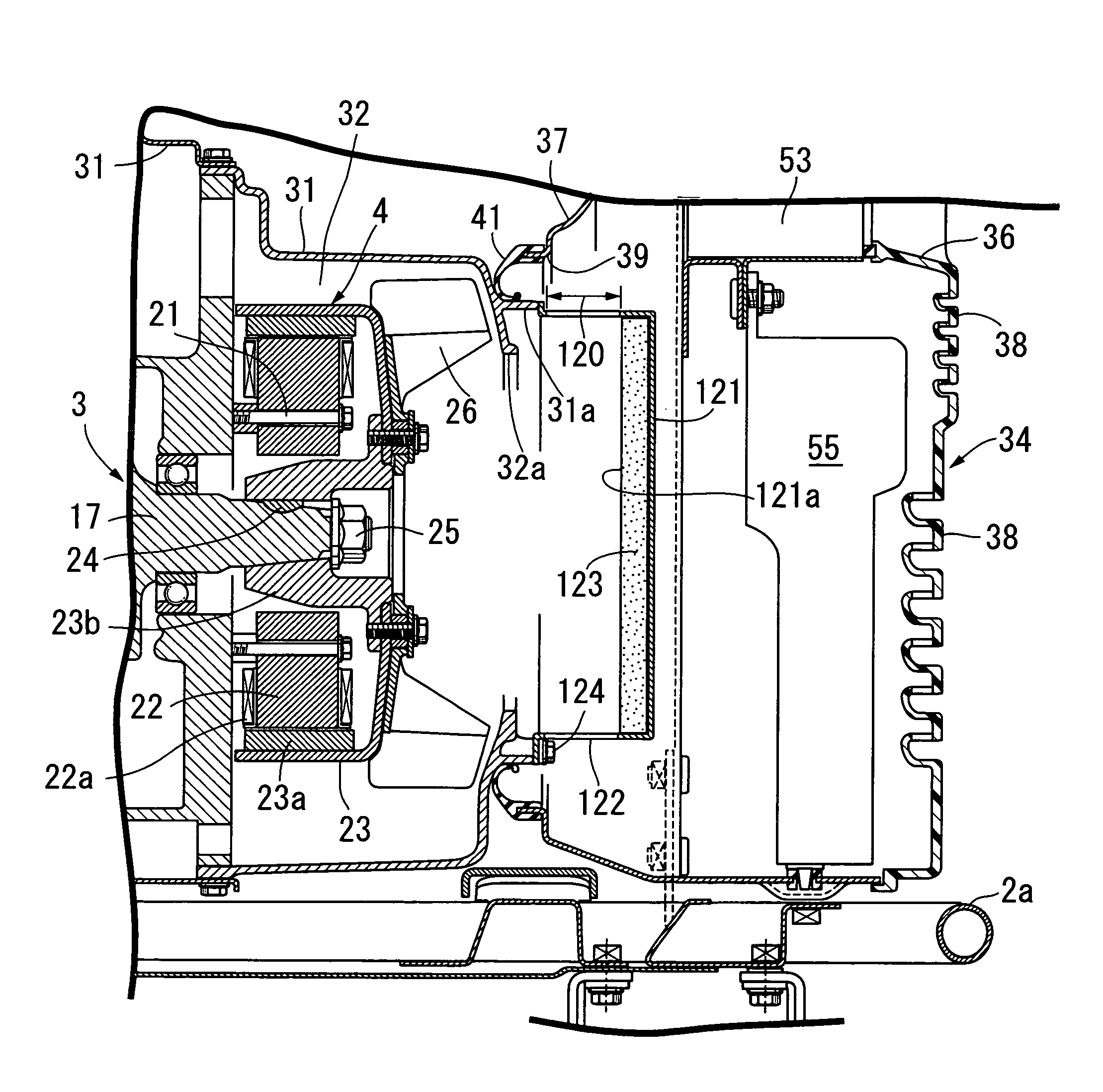
[0116]In the second embodiment, a large number of recesses 125 and a large number of projections 126 are alternately formed on a surface 121a of a silencing plate 121 or a sound-absorbing material 123 opposite the inlet 32a of the cooling-air passage 32. Because the other components are the same as those of the first embodiment, components in FIG. 22 corresponding to those of the first embodiment are designated by the same reference numerals to omit the overlapping description.

[0117]With the second embodiment, when the operational noise leaked from the inlet 32a of the cooling-air passage 32 collides against the recesses 125 and the projections 126, the reflection and collision of the noise are repeated between the recesses 125 and the projections 126 to reduce the energy of the noise level, thereby improving the silencing effect.

third embodiment

[0118]the present invention shown in FIG. 23 will now be described.

[0119]In the third embodiment, a surface 121a of a silencing plate 121 opposite the inlet 32a of the cooling-air passage 32 is formed to have a spherical concave surface. Because the other components are the same as those of the first embodiment, components in FIG. 23 corresponding to those of the first embodiment are designated by the same reference numerals to omit the overlapping description.

[0120]With the third embodiment, the noise leaked from the inlet 32a of the cooling-air passage 32 collides against the silencing plate 121 to reflect therefrom and is oriented to a central portion of the inlet 32a, thereby effectively preventing sound leakage from the ventilation gap 120.

fourth embodiment

[0121]Lastly, the present invention shown in FIG. 24 will be described.

[0122]In the fourth embodiment, a pair of labyrinth members 127 and 128 opposite each other with a ventilation gap 120 provided therebetween are connected to a silencing plate 121. Because the other components are the same as those of the first embodiment, components in FIG. 24 corresponding to those of the first embodiment are designated by the same reference numerals to omit the overlapping description.

[0123]With the fourth embodiment, the operational noise leaked to the ventilation gap 120 is absorbed by the pair of the concavo-convex inner surfaces of the labyrinth members 127 and 128 opposing each other, thereby preventing sound from leaking through the ventilation gap 120.

[0124]The present invention is not limited to the above-described embodiments, and various modifications in design may be made without departing from the scope of the invention.

[0125]For example, the air cleaner 45 may be fixedly supported...


PUM


Abstract

An engine and a generator driven by the engine are resiliently supported on a frame. A duct member is integrally attached to the engine and the generator to define a continuous cooling-air passage between the duct member and outer peripheral surfaces of the engine and the generator. A cooling fan is disposed on an inlet side of the cooling-air passage. A silencing plate is integrally attached to the duct member and faces an inlet of the cooling-air passage with a ventilation gap defined therebetween. The silencing plate has an area opposing the inlet that is larger than an opening area of the inlet.

Description

RELATED APPLICATION DATA[0001]The present invention is based upon Japanese priority application No. 2006-231010, which is hereby incorporated in its entirety herein by reference.BACKGROUND OF THE INVENTION[0002]1. Field of the Invention[0003]The present invention relates to an engine-driven work machine driven by an engine, the work machine and the engine being supported on a frame with a resilient member interposed therebetween. The work machine includes a duct member integrally attached to the engine and the work machine so as to define a continuous cooling-air passage between the duct member and outer peripheral surfaces of the engine and the work machine. A cooling fan is disposed on an inlet side of the cooling-air passage and feeds cooling air, under pressure, toward the engine and the work machine. The work machine driven by the engine encompasses a generator, an air compressor, a storage pump, and the like.[0004]2. Description of the Related Art[0005]Japanese Patent Applicat...

Claims


Application Information

Patent Timeline
Patent Type & Authority Patents(United States)
IPC IPC(8): F01P7/02F01N1/24
CPCF01P5/06F01P11/10F01P11/12F02B63/04F01N2260/022F01P2001/005F02B63/044F02B2063/045
Inventor ITO, TAKASHIONODERA, TAIYO
Owner HONDA MOTOR CO LTD
Why Eureka
Try Eureka