Knee walker

a walker and support technology, applied in the direction of steering devices, frictional rollers based transmission, cycle equipment, etc., can solve the problems of user loss of balance and fall, and achieve the effect of positive steering control and reduced effor

Active Publication Date: 2010-08-24
ESSENTIAL MEDICAL SUPPLY
View PDF29 Cites 41 Cited by
  • Summary
  • Abstract
  • Description
  • Claims
  • Application Information

AI Technical Summary

Benefits of technology

[0003]With the foregoing in mind, the present invention advantageously provides a knee walker which offers the user positive steering control and greatly reduces the effort required from the user to change the directional movement of the device.
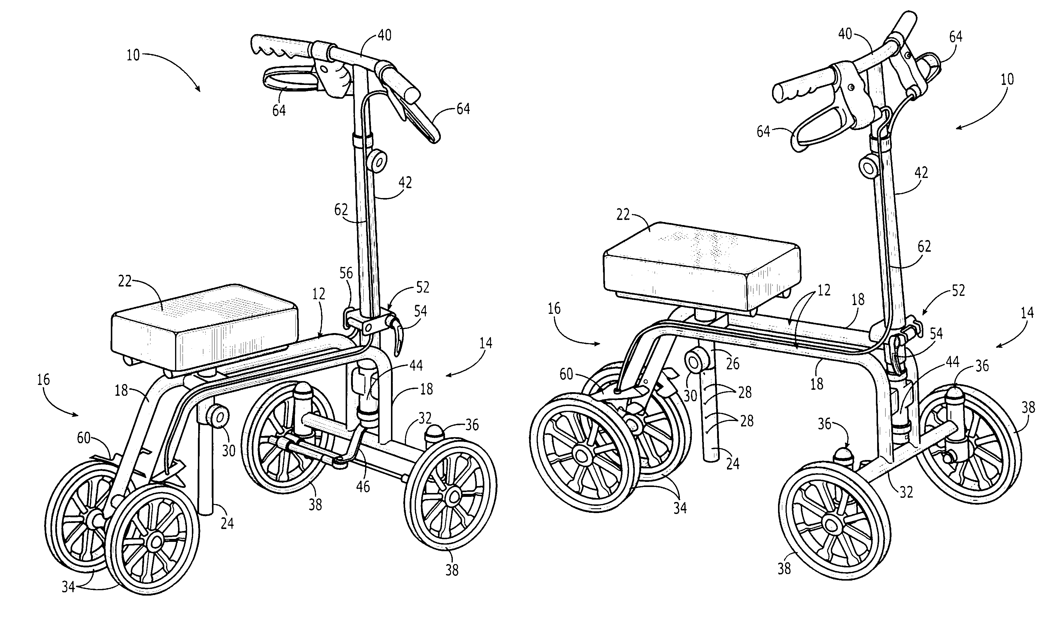
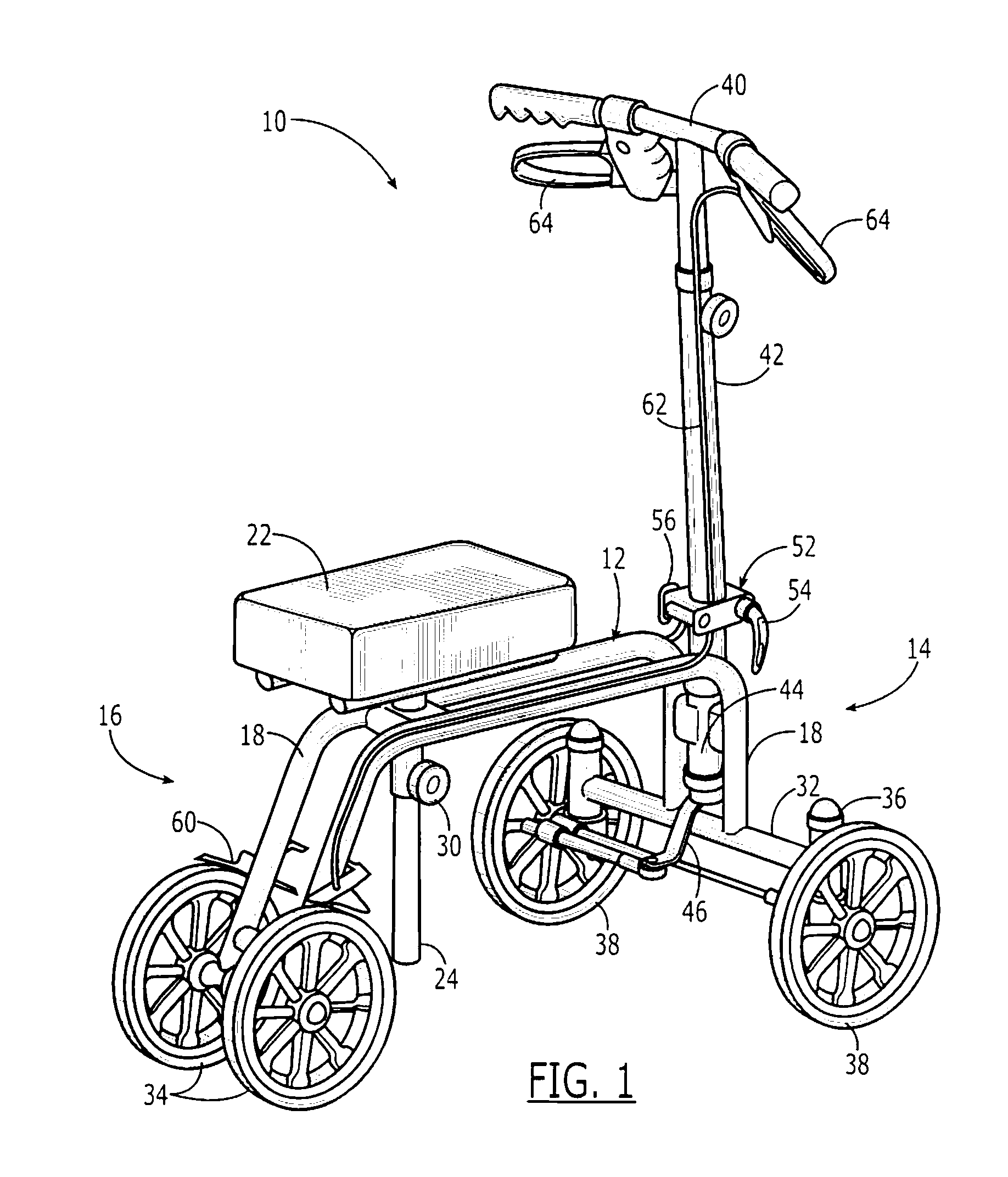
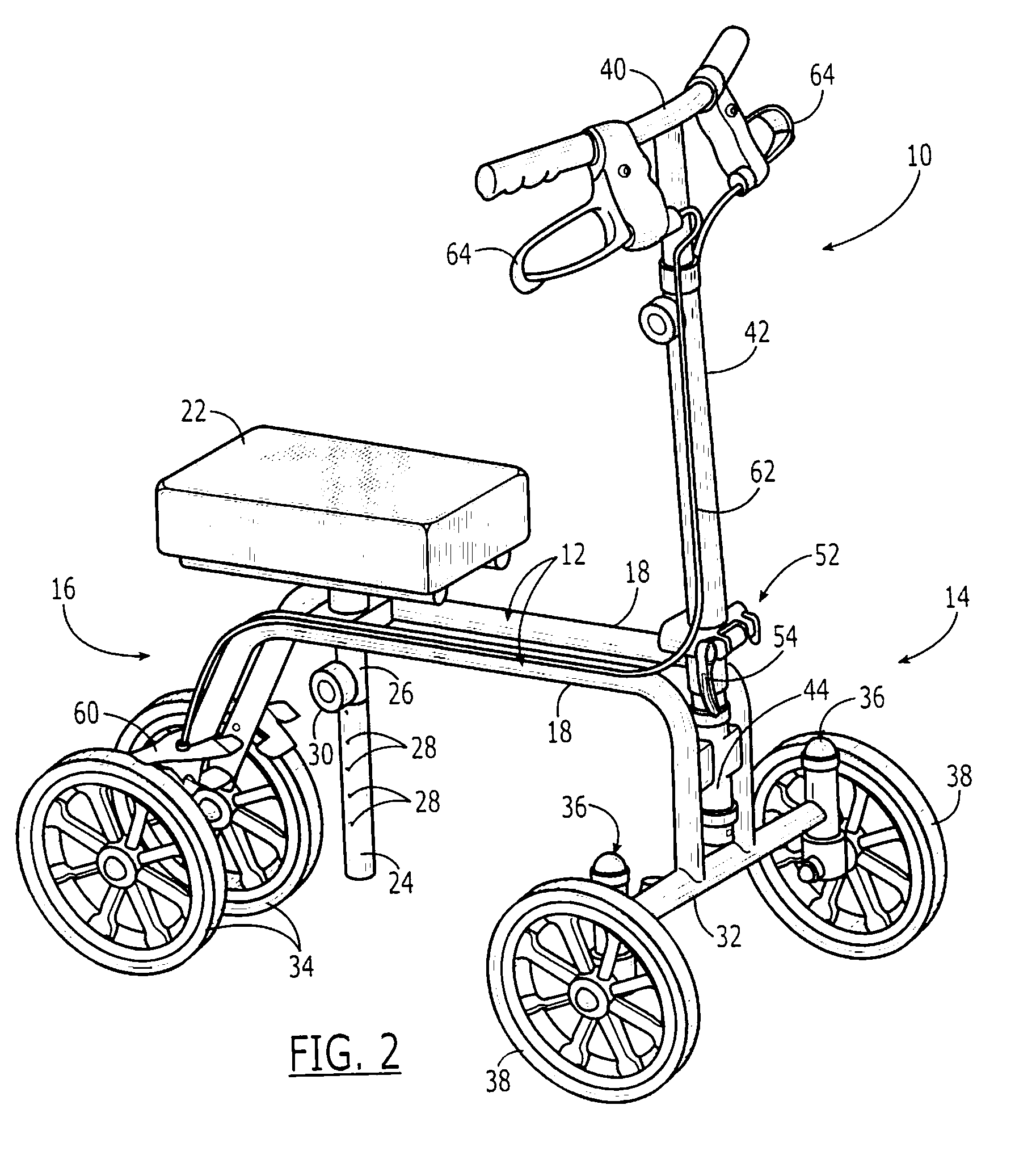
[0004]Accordingly, the present invention provides a knee walker comprising a frame having a front end and a rear end spaced apart therefrom. A cushion is supported on an upper side of the frame, preferably on a height adjustable post. A front crossmember is supported on a lower side of the front end of the frame and extends laterally outwardly therefrom. Two rear wheels are rotatably connected adjacent the rear end of the frame. The knee walker includes two front spindles, each positioned at an end of the front crossmember and approximately perpendicular thereto. Two front wheels are each pivotally connected to one of the two front spindles, the two front wheels farther spaced apart than the two rear wheels. A handlebar is borne at an upper end of a height adjustable shaft rotatably connected to the front end of the frame. A steering gear is located at the front end of the frame and is responsively engaged with the rotatable handlebar shaft. A steering arm is actuated by the steering gear responsive to the handlebar and its motion is transferred to the front wheels by a steering rod connecting the steering arm and one of the two front spindles, so as to pivot one associated front wheel responsive to the steering arm. The steering system includes a tie rod which links the two front spindles together, responsively to the steering rod. Accordingly, as the one wheel pivots, the tie rod steering linkage actuates the second wheel to pivot as well, thereby allowing the knee walker to turn. The tie rod linkage prevents the front wheels from turning beyond a certain degree of pivot, thereby guarding against user oversteering which could cause a loss of balance and a fall.

Problems solved by technology

This effort may also cause the user to employ body lean to affect the directional movement of the device, an action which could lead the user to lose balance and fall.

Method used


Image

  • Knee walker
  • Knee walker
  • Knee walker

Examples


Embodiment Construction

[0017]The present invention will now be described more fully hereinafter with reference to the accompanying drawings, in which preferred embodiments of the invention are shown. Unless otherwise defined, technical and scientific terms used herein have the same meaning as commonly understood by one of ordinary skill in the art to which this invention pertains. Although methods and materials similar or equivalent to those described herein can be used in the practice or testing of the present invention, suitable methods and materials are described below. In addition, the materials, methods and examples given are illustrative in nature only and not intended to be limiting. Accordingly, this invention may be embodied in many different forms and should not be construed as limited to the illustrated embodiments set forth herein. Rather, these illustrated embodiments are provided solely for exemplary purposes so that this disclosure will be thorough and complete, and will fully convey the sc...


PUM


Abstract

A knee walker includes a frame; a cushion; a front crossmember; two rear wheels; two front spindles and two front wheels each pivotally connected to one of the two front spindles. Positive steering is provided by a handlebar rotatably connected to the front end of the frame; a steering gear responsively engaged with the rotatably connected handlebar shaft; a steering arm actuated by the steering gear responsive to the handlebar; a steering rod connecting the steering arm and one of the two front spindles, so as to pivot one associated front wheel responsive to the steering arm; and a tie rod linking the two front spindles responsively to the steering rod.

Description

FIELD OF THE INVENTION[0001]The present invention relates to the field of ambulatory devices for the physically impaired and, more particularly, to a knee support walker apparatus.BACKGROUND OF THE INVENTION[0002]Many previously described devices provide walking assistance for those with physical impairments. Previous devices include wheel chairs, wheeled walkers and wheeled scooters, that is, a wheeled device which provides support for one knee or for the stump of an amputated limb, a type of device also known as a knee walker. Many of the prior devices include wheels which swivel so as to allow the user to guide the device in a desired direction or to make a turn. Typically, devices having more than one front wheel have employed static handlebars, that is, the user's hands rest on either handles or on a handlebar which does not turn to guide the direction of the device. Such static handlebars coupled with swiveling wheels still require that the user of a knee walker use his / her go...

Claims


Application Information

Patent Timeline
Patent Type & Authority Patents(United States)
IPC IPC(8): B62K17/00
CPCA61H3/04A61H2003/005A61H2003/046
Inventor HOEPNER, JOHN M.LIN, CHING-HSU
Owner ESSENTIAL MEDICAL SUPPLY
Why Eureka
Try Eureka