Apparatus for and method of controlling power train, and storage medium storing program for implementing the method

a technology of power train and power train, which is applied in the direction of mechanical apparatus, instruments, transportation and packaging, etc., can solve the problems of insufficient prevention of the reduction of the output torque of the automatic transmission in the inertia phase of a downshift, and the shock occurs, so as to reduce the shock

Inactive Publication Date: 2010-08-24
TOYOTA JIDOSHA KK
View PDF12 Cites 22 Cited by
  • Summary
  • Abstract
  • Description
  • Claims
  • Application Information

AI Technical Summary

Benefits of technology

[0010]An object of the present invention is to provide an apparatus for and a method of controlling a power train that reduce the shock that can occur in the course of a shift, and a storage medium storing a program for implementing the method.
[0012]According to the first or fifth aspect, an inertia phase is started at the time of the downshift by gradually reducing the torque capacity of the frictional engagement device that is brought from an engaged state into a disengaged state. When at least one of the rate of change in the rotation speed of the rotary member (the input shaft, for example) of the automatic transmission, and the rate of change in the speed ratio of the automatic transmission has reached a predetermined value, the gradual reduction of the torque capacity of the frictional engagement device is stopped. Thus, it is possible to prevent the torque capacity of the frictional engagement device from being unnecessarily reduced. Accordingly, it is possible to keep small the variation in the output torque from the automatic transmission during transition from an inertia phase to a torque phase by preventing the torque transmitted to the output shaft from being reduced during the inertia phase. Thus, it is possible to provide an apparatus for and a method of controlling a power train that reduce the shock that can occur at the time of a shift.
[0014]According to this aspect, after the gradual reduction of the torque capacity of the frictional engagement device is stopped, the torque capacity of the frictional engagement device is controlled according to input torque supplied to the automatic transmission, and the torque capacity of the frictional engagement device is controlled so that at least one of the rate of change in the rotation speed of the rotary member of the automatic transmission, and the rate of change in the speed ratio of the automatic transmission is maintained at the predetermined value. Thus, it is possible to prevent excess and deficiency of the torque capacity of the frictional engagement device in relation to the input torque supplied to the automatic transmission. In addition, it is possible to prevent the torque capacity of the frictional engagement device from being unnecessarily reduced. Thus, it is possible to keep small the variation in the output torque from the automatic transmission during transition from an inertia phase to a torque phase by preventing the torque transmitted to the output shaft from being reduced in the inertia phase. As a result, it becomes possible to reduce the shock that can occur at the time of a shift.
[0016]With these aspects, the power train is controlled so that rotation speed of an input shaft of the automatic transmission becomes higher than a synchronized rotation speed with respect to the lower gear within a predetermined range in an inertia phase of the downshift. In addition, control is performed so that torque capacity of the first frictional engagement device that is brought from an engaged state into a disengaged state at the time of the downshift is gradually reduced, and that torque capacity of the second frictional engagement device that is brought from a disengaged state into an engaged state is gradually increased when the rotation speed of the input shaft of the automatic transmission becomes higher than the synchronized rotation speed with respect to the lower gear within the predetermined range in the inertia phase of the downshift. Thus, it is possible to start the gradual reduction of the torque capacity of the first frictional engagement device and the gradual increase of the torque capacity of the second frictional engagement device under conditions in which the rotation speed of the input shaft of the automatic transmission is higher than the synchronized rotation speed with respect to the lower gear, and thus to reduce the rotation speed of the input shaft to the synchronized rotation speed. Reduction of the rotation speed of the input shaft to the synchronized rotation speed is controlled more easily than increase of the rotation speed of the input shaft to the synchronized rotation speed. Thus, it is possible to keep small the variation in the output torque from the automatic transmission during a shift by smoothly reducing the rotation speed of the input shaft to the synchronized rotation speed. Moreover, control is performed so that reduction of the amount of boost of the output torque from the driving power source is started after the rotation speed of the input shaft is reduced to the synchronized rotation speed. As a result, during the period from when gradual reduction of the torque capacity of the first frictional engagement device and gradual increase of the torque capacity of the second frictional engagement device are started to when rotation speed of the input shaft is reduced to the synchronized rotation speed, that is, at the final stage of the inertia phase, the output torque from the engine is not varied, and only the torque capacities of the two frictional engagement devices are varied. Varying only the torque capacities of two frictional engagement devices is controlled more easily than varying the output torque from the driving power source in addition to the torque capacities of two frictional engagement devices. Thus, it is possible to keep variation in the output torque from the automatic transmission small. Thus, it is possible to provide an apparatus for and a method of controlling a power train that reduce the shock that can occur at the time of a shift.
[0018]According to the third or seventh aspect, in the inertia phase, the torque capacity of the first frictional engagement device is gradually reduced, and the torque capacity of the second frictional engagement device is gradually increased, while maintaining a relation between the torque capacities such that the output torque from the automatic transmission at the end of the inertia phase and the output torque therefrom at the start of the subsequent torque phase are equalized to each other. In this way, the curves of the output torque from the automatic transmission are smoothly connected at the point of the transition from an inertia phase to a torque phase. Thus, it is possible to keep small the variation in the output torque from the automatic transmission during transition from an inertia phase to a torque phase. As a result, it becomes possible to provide an apparatus for and a method of controlling a power train that reduce the shock that can occur at the time of a shift.
[0020]According to the fourth or eighth aspect, reduction of the amount of boost of the output torque from the driving power source and reduction of torque capacity of the frictional engagement device in a torque phase of the downshift are synchronously started. Similarly, the reduction of the amount of boost of the output torque from the driving power source and the reduction of the torque capacity of the frictional engagement device in the torque phase of the downshift are synchronously completed. Thus, it is possible to prevent the torque capacity of the frictional engagement device from becoming excessive or insufficient in relation to the output torque from the driving power source, that is, the input torque supplied to the automatic transmission during the torque phase. Thus, it is possible to keep variation in the output torque from the automatic transmission small. As a result, it becomes possible to provide an apparatus for and a method of controlling a power train that reduce the shock that can occur at the time of a shift.

Problems solved by technology

When the output torque is increased stepwise, a shock occurs.
However, even when such a torque boost operation is performed during a shift as in the case of the shift controller described in JP-A-2004-316838, gradual reduction of torque capacity (engagement force) of a frictional engagement device in the course of a shift can cause a situation where the reduction in the output torque from the automatic transmission in an inertia phase of a downshift is not sufficiently prevented.

Method used


Image

  • Apparatus for and method of controlling power train, and storage medium storing program for implementing the method
  • Apparatus for and method of controlling power train, and storage medium storing program for implementing the method
  • Apparatus for and method of controlling power train, and storage medium storing program for implementing the method

Examples


Embodiment Construction

[0034]An embodiment of the present invention will be described below with reference to drawings. In the following description, the same parts are denoted by the same reference numeral. The name and function of these parts are the same. Hence, detailed description of such parts will not be repeated.

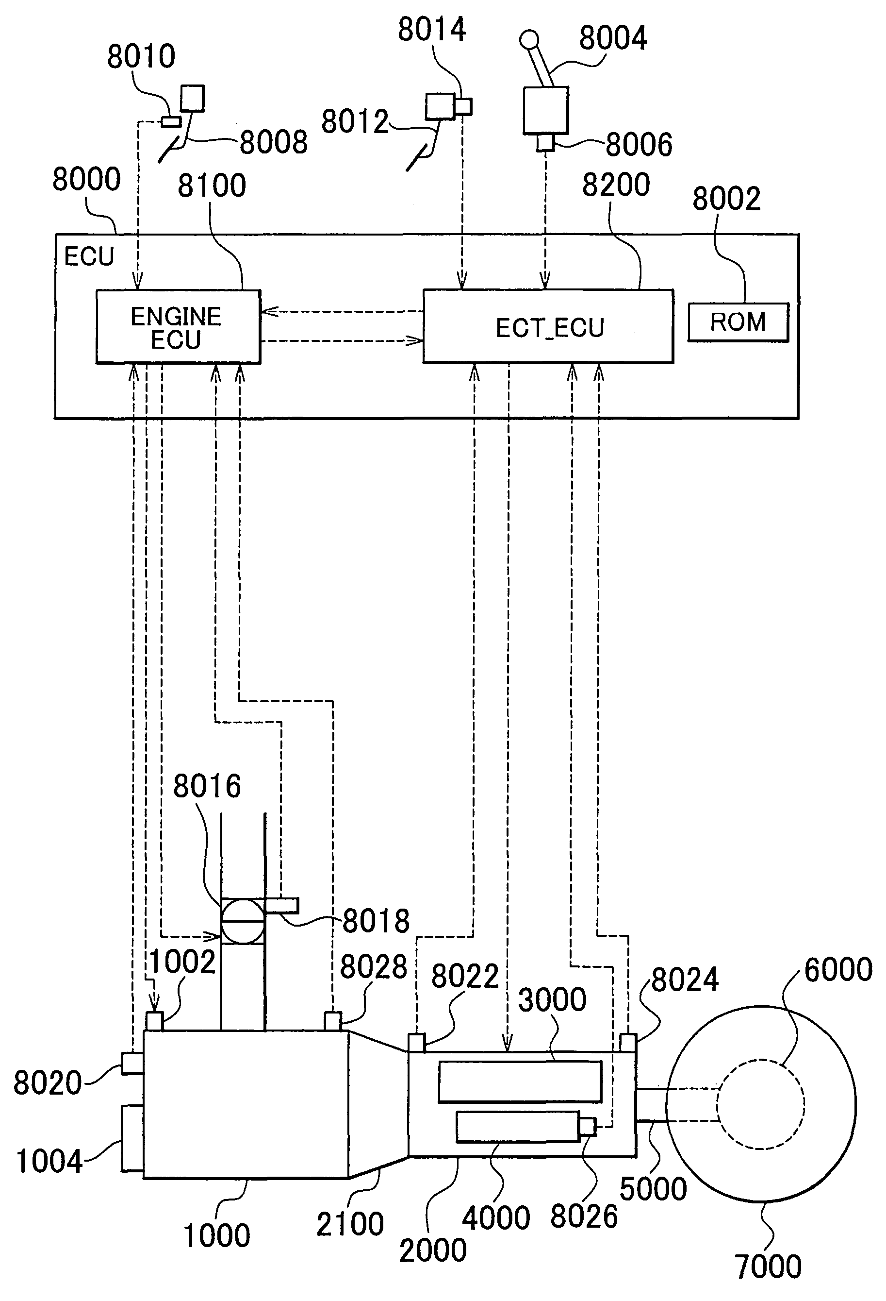
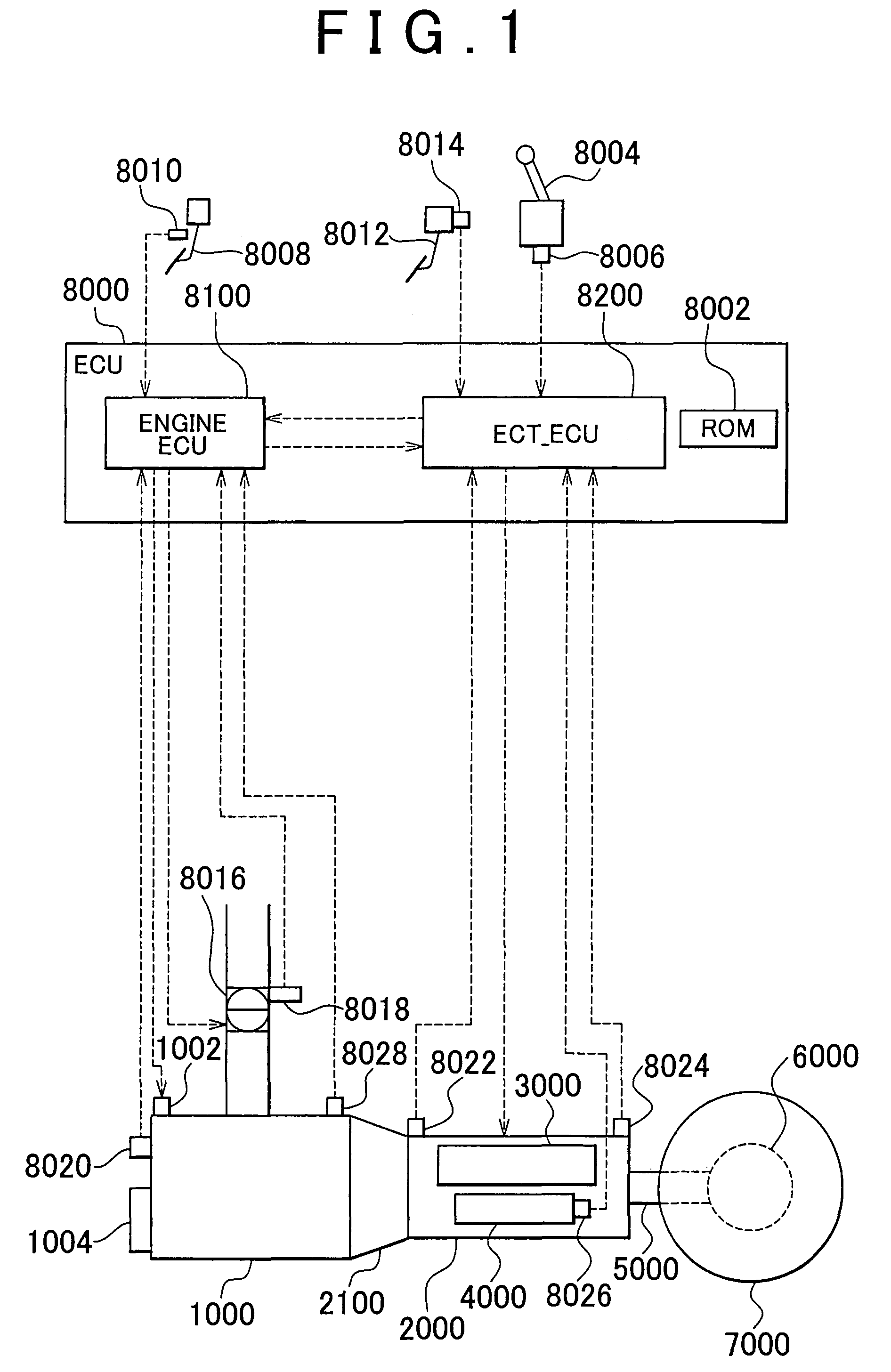
[0035]Referring to FIG. 1, a vehicle in which a controller according to the embodiment of the present invention is installed will be described. The vehicle is an FR (Front-engine, Rear-drive) vehicle. The vehicle may be a vehicle that is not an FR vehicle.

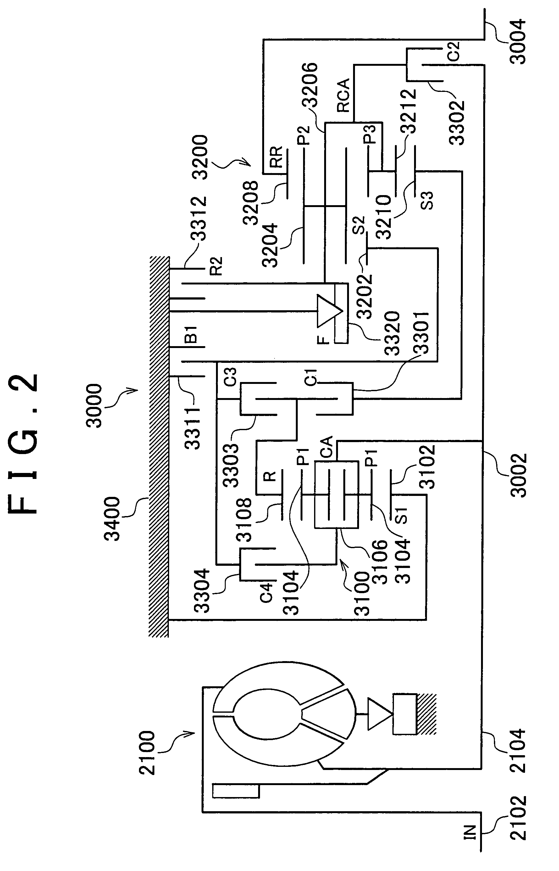
[0036]The vehicle includes: an engine 1000; an automatic transmission 2000; a torque converter 2100; a planetary gear unit 3000 constituting part of the automatic transmission 2000; a hydraulic circuit 4000 constituting part of the automatic transmission 2000; a propeller shaft 5000; a differential gear 6000; rear wheels 7000; and an ECU (Electronic Control Unit) 8000.

[0037]In this embodiment, a power train includes the engine 1000 and th...


PUM


Abstract

An ECU executes a program for implementing a method that includes: a step of performing control so that torque capacity Tch of a frictional engagement device that is brought from an engaged state into a disengage state by a downshift operation is gradually reduced to start an inertia phase when a power-on downshift is performed; and a step of stopping the gradual reduction of the torque capacity Tch when the rate of change in an input shaft rotation speed NI of an automatic transmission has reached a desired rate of change ΔN(1). Variation in output torque is kept small, and the shock that can occur at the time of a shift is thus reduced.

Description

INCORPORATION BY REFERENCE[0001]The disclosure of Japanese Patent Application No. 2006-338535 filed on Dec. 15, 2006 including the specification, drawings and abstract is incorporated herein by reference in its entirety.BACKGROUND OF THE INVENTION[0002]1. Field of the Invention[0003]The present invention relates to an apparatus for and a method of controlling a power train, and a storage medium in which a program for implementing the method is stored. More specifically, the present invention relates to a technology for controlling a power train that is connected to an automatic transmission, and that includes a driving power source whose output torque is boosted during a downshift.[0004]2. Description of the Related Art[0005]In a vehicle on which an automatic transmission is mounted in which one of a plurality of gears is established by selectively engaging a plurality of frictional engagement devices, a gear is established corresponding to a combination of the frictional engagement...

Claims


Application Information

Patent Timeline
Patent Type & Authority Patents(United States)
IPC IPC(8): B60W10/00B60W10/04B60W10/06B60W10/10B60W10/11B60W10/115F16H59/42F16H59/68F16H61/04F16H61/68F16H61/684F16H61/686F16H63/50
CPCB60W10/06B60W30/19F16H61/0437F16H63/502B60W10/115Y10T477/676F16H61/686F16H2200/006F16H2200/2007F16H2306/42Y10T477/6407Y10T477/69367Y10T477/69373Y10T477/693636Y10T477/69364Y10T477/69366F16H61/04F16H61/00
Inventor IWATSUKI, KUNIHIROTOKURA, TAKAAKI
Owner TOYOTA JIDOSHA KK
Why Eureka
Try Eureka