Dust collector cup of fall centrifugal separation type

a centrifugal separation and dust collector technology, applied in the direction of liquid degasification, separation process, cleaning filter means, etc., can solve the problems of increased material cost, insufficient centrifugal force generated in dust collectors, and insufficient volume, so as to reduce the contiguous volume of products, reduce air pressure loss, and compact structure

Inactive Publication Date: 2010-08-24
WANG YUEDAN
View PDF39 Cites 60 Cited by
  • Summary
  • Abstract
  • Description
  • Claims
  • Application Information

AI Technical Summary

Benefits of technology

[0006]The object of this invention is to provide a dust collector cup working in the principle of fall centrifugal separation to solve the technical problems of existing dust collector cups such as poor separation effect, great in volume and weight, unable to meet the development and manufacture requirements of vertical type or portable type dust collector products, great raw material consumption and high cost.
[0009]Since there is a certain fall difference between the inlet of cup body and that of the outlet tube, certain air pressure difference exists in the two inlets. Air with dust, after entering the dust cup, will generate a swift downward spiral wind, and the dust will be thrown towards the circumferential wall under centrifugal force and gravity, and falling to the bottom of the dust-collecting cavity of the cup body. Due to the separation effect of the isolating shield, dust falling into the cavity is hard to be thrown up and goes into the inlet of separator under the effect of the upper spiral wind. Only small amount of fine dust particles will be released from the outlet of the outlet tube with air flow, and settle on the filter piece. Thus, the effect of dust separation will be improved to a great extent. The dust collector cup of this invention features simple structure, low cost and small volume.
[0011]An inner tube can be coaxially installed in said outlet tube, the height of which should be lower than that of the outlet tube. The inlet of the separator is connected with the outlet of the dust cup via the inner tube to constitute a split two-stage separation dust collector cup. The dust removal device, which is used to separate dust and air, adopts the pattern of inner tube coaxially laid out with outlet tube, so that the contour volume of the product is reduced. The inlet of the separator is used both as the outlet of clean air and the inlet of the inner dust cavity at the same time, getting rid of the transverse connecting duct in current technologies, facilitating to reduce air pressure loss. Compared with current technologies, this invention possesses a dust collector cup with two-stage separation function, which is more compact in structure, so that the contour volume and the raw material consumption can be greatly reduced. And it is especially suitable for the development and manufacture of vertical or portable dust collector products.
[0012]Furthermore, the described inlet of the separator is an annular structure consisting of vanes smoothly arranged in an annular and spiral array. Vanes arranged in a spiral manner are configured for the inlet of the separator, so that spiral wind will be generated in the inner tube and the inner dust cavity. The cleaning effect of the separated dust is further improved.
[0014]Moreover, one spiral structure rotating up and down is configured in the extension tube and after the second-stage separation, because of the effect of the spiral structure in the extension tube, the separated air continues to swirl upward. If that part of air still carries a slight amount of fine dust, and when the air rises to the upper part of the extension tube, the swirl radius suddenly increases and the air pressure declines. So the centrifugal force once again separates and throws the extremely small amount of fine dust from the air onto the inner wall of the outlet tube, which will swirl along the wall and fall down. The separation effect can be further improved.

Problems solved by technology

The inlet of the centrifuge usually corresponds to that of the dust cup; therefore, the centrifugal force generated in the dust cup is not great enough.
Therefore, it is obvious that there are defects and insufficiency of too great volume, increased material cost and being not suitable for vertical type or portable type dust collector.

Method used


Image

  • Dust collector cup of fall centrifugal separation type
  • Dust collector cup of fall centrifugal separation type
  • Dust collector cup of fall centrifugal separation type

Examples


example 1

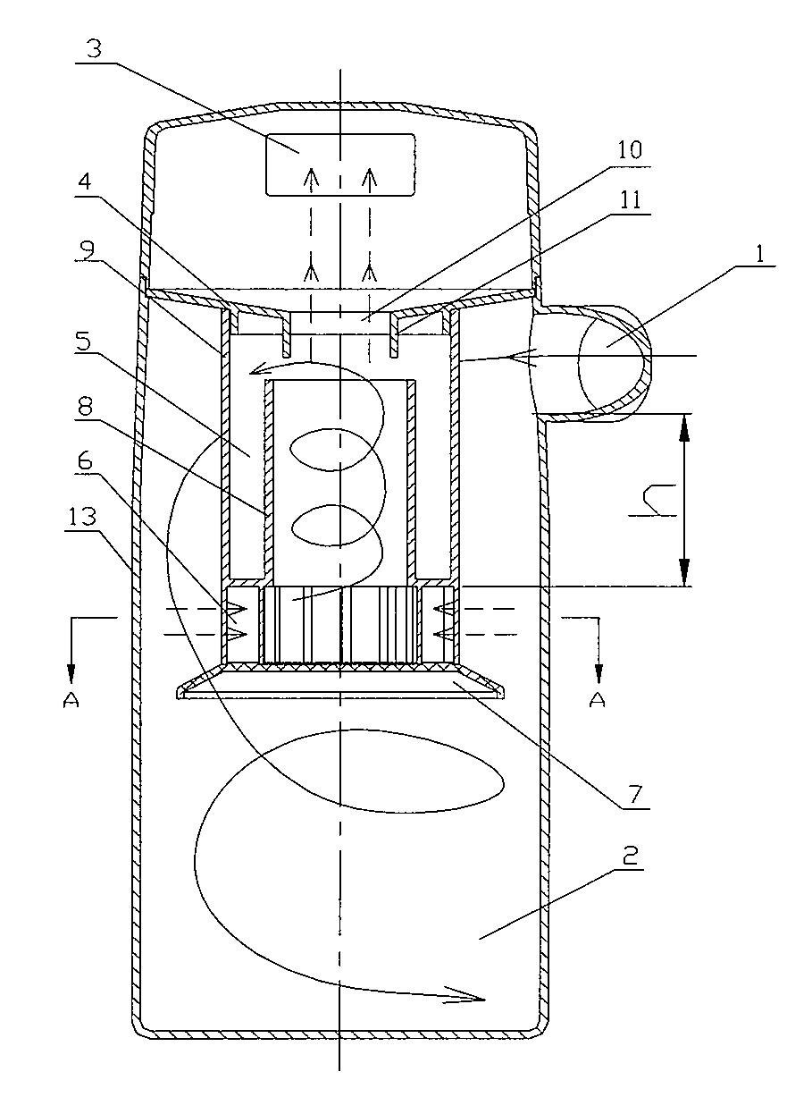
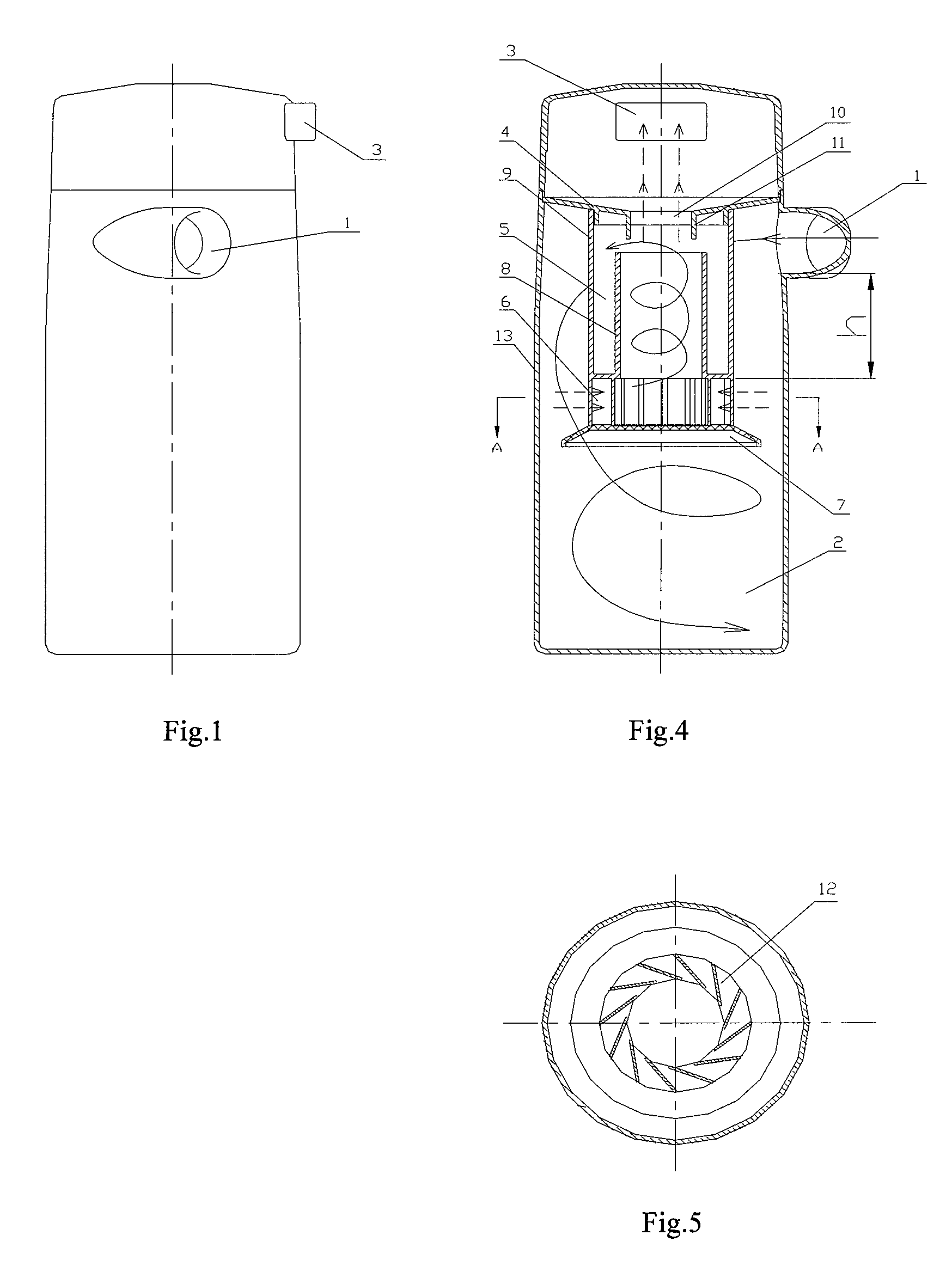
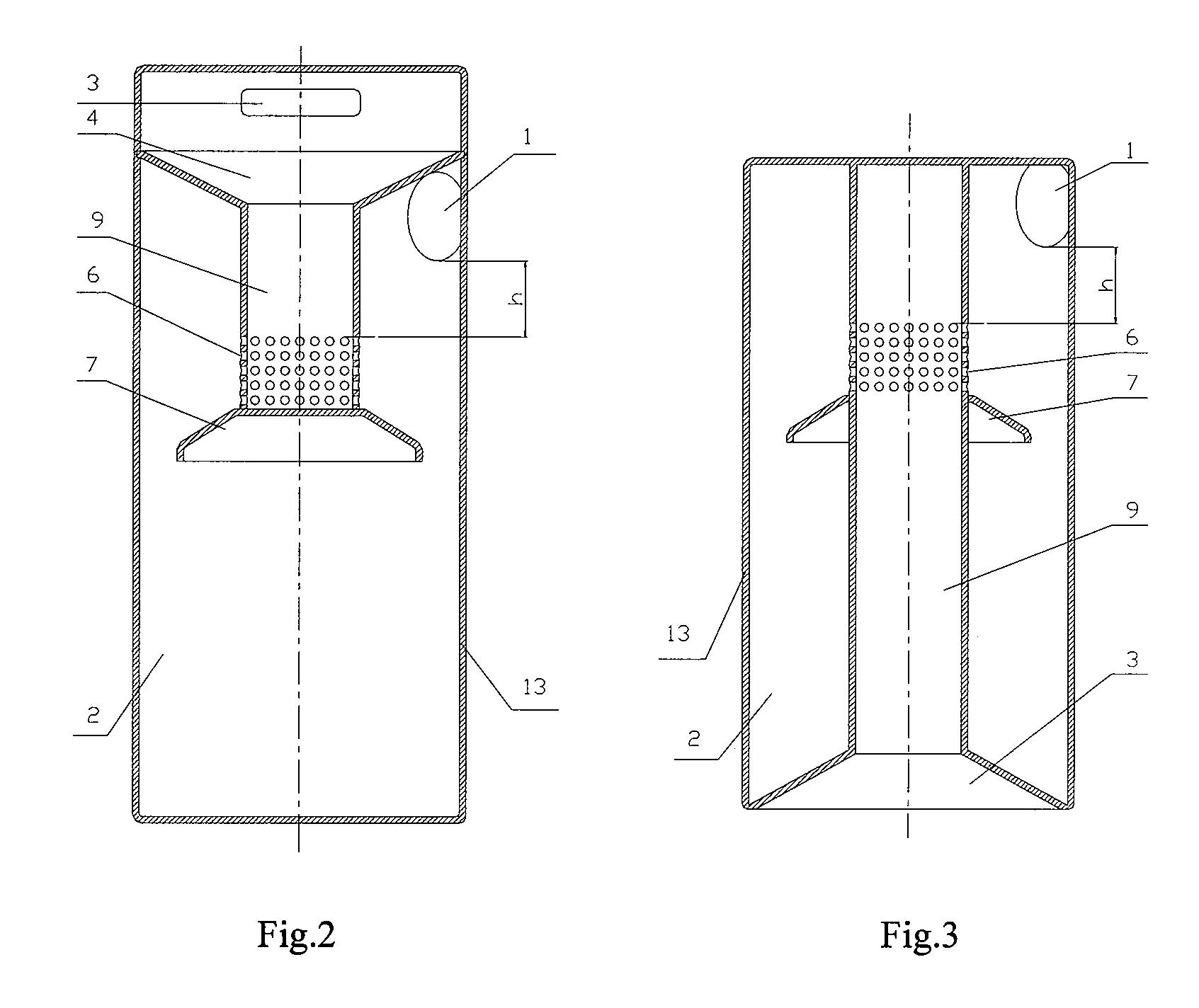
[0035]Horizontal dust collector with a depth from the lower end of the dust cup inlet to the bottom of the cup is 130 mm. The fall height h between the horizontal positions of the lower end of the dust cup inlet and the upper end of the inlet of the separator is supposed to be 30 mm.

example 2

[0036]Vertical dust collector with a depth from the lower end of the dust cup inlet to the bottom of the cup is 270 mm. The fall height h between the horizontal positions of the lower end of the dust cup inlet and the upper end of the inlet of the separator is supposed to be 140 mm.

example 3

[0037]Vertical dust collector with a depth from the lower end of the dust cup inlet to the bottom of the cup is 185 mm. The fall height h between the horizontal positions of the lower end of the dust cup inlet and the upper end of the inlet of the separator is supposed to be 45 mm (a datum between 30-140 with very good effect is given).


PUM

PropertyMeasurementUnit
heightaaaaaaaaaa
depthaaaaaaaaaa
heightaaaaaaaaaa

Abstract

A dust collector cup working in the principle of fall centrifugal separation, consists of cup body (13), outlet (3) on the cup body (13), inlet (1) tangential to the circumferential wall of the cup body (13), and a separator settled in the cup body (13). The separator is composed of outlet tube (9), inlet (6) on the wall of the outlet tube (9), and the isolating shield (7) under the inlet (6) of the outlet tube (9), with the outlet tube (9) linked to the outlet (3) of the cup body (13). The fall between the horizontal positions of the lower end of inlet of the cup body (13) and the upper end of the inlet (6) of the outlet tube (9) is 0-140 mm.

Description

CROSS-REFERENCE TO RELATED APPLICATIONS[0001]This is the U.S. National Stage of International Application No. PCT / CN06 / 000003, filed Jan. 4, 2006, which is based on and claims priority to Chinese Application Nos. 200510049880.2 and 200510049881.7, both filed May 27, 2005.FIELD OF THE INVENTION[0002]This invention relates to a dust collector cup working in the principle of fall centrifugal separation. More particularly, the present invention relates to a dust collector cup which utilizes the principle of fall difference to increase the centrifugal force that separates dust and air, so as to improve the separation effect.DESCRIPTION OF THE PRIOR ART[0003]Common centrifugal dust collectors utilizing vacuum principle send air with dust or foreign matters into the inlet of dust cup along tangential direction and generate a centrifugal vortex flow in the dust cup, so that comparatively large and heavy particles or filth will deposit at the bottom of the dust cup, which will be cleaned up....

Claims


Application Information

Patent Timeline
Patent Type & Authority Patents(United States)
IPC IPC(8): B01D50/00
CPCA47L9/1608A47L9/1633A47L9/165A47L9/1666Y10S55/03
Inventor LANG, WEIGUO
Owner WANG YUEDAN
Why Eureka
Try Eureka