Method for conducting maintenance on a chromatography column

a chromatography column and chromatography technology, applied in the direction of separation processes, instruments, filtration separation, etc., can solve the problems of high undesirable, manual removal and re-introduction poses a potential safety risk to operators, and the presence of such hoists or cranes in biopharmaceutical manufacturing facilities, etc., to improve the maneuverability of the handling device and facilitate the operation of the handling device. smooth

Active Publication Date: 2010-08-24
CYTIVA SWEDEN AB
View PDF8 Cites 16 Cited by
  • Summary
  • Abstract
  • Description
  • Claims
  • Application Information

AI Technical Summary

Benefits of technology

[0036]Preferably, the step of removing the bed support from the column and / or the step of returning the bed support to the column with the handling device is carried out without substantially tilting the bed support. This reduces operator exposure beneath the suspended load and facilitates mechanical handling of the bed support. The term ‘without substantially tilting’ as used herein means ‘tilting at an angle of no more than 5° to the horizontal’.
[0056]Preferably, the step of removing the bed support from the column and / or the step of returning the bed support to the column with the handling device is carried out without substantially tilting the bed support. This reduces operator exposure beneath the suspended load and facilitates mechanical handling of the bed support. The term ‘without substantially tilting’ as used herein means ‘tilting at an angle of no more than 5° to the horizontal’.
[0062]In a further aspect, the one or more arms additionally comprise a pad for resting the column component thereon. This prevents damage to the column component. Preferably, the one or more arms are extendable.
[0065]In another aspect, the wheels are independently rotatable to improve the maneuverability of the handling device. Preferably, the wheels are independently lockable. Preferably, the wheels are independently levelable; for example, by means of jacking devices attached to each wheel. Levelable wheels provide easier and smoother operation of the handling device on surfaces which are uneven such as clean rooms with sloping floors. More preferably, the wheels are powered by electrical means.

Problems solved by technology

As these components can be very heavy (bed supports, for example, may weigh in excess of 100 kg), their manual removal and re-introduction poses a potential safety risk to operators who must physically support and manipulate them.
The use of heavy overhead lifting equipment to disassemble the column in order to carry out internal maintenance is, in itself, highly undesirable.
Operator safety is obviously a concern when heavy equipment is lifted overhead and technicians exposed below.
Moreover, the requirement to use heavy lifting equipment imposes constraints on housing such columns, sufficient overhead space and support being required to accommodate hoists or cranes.
Further, the presence of such hoists or cranes in GMP facilities used for biopharmaceutical manufacturing (such facilities also being known as “clean rooms”) is highly undesirable due to the shedding of particulate matter such as dirt during their operation and maintenance.
However, the system described in U.S. Pat. No. 6,736,974 has significant disadvantages associated with it by virtue of its design.
This clearly poses a significant safety risk to the operator, particularly where the operator's arm or head is exposed below the suspended or supported load.
Furthermore, once the column tube / cylinder or adapter assembly has been raised from the base assembly or tube, respectively, removal of the heavy bed support or distributor from the column can only be accomplished by tilting the bed support or distributor at an angle to negotiate the hydraulic drive pistons or safety rods.
Removal of these internal components, which could weigh in excess of 100 kg, requires considerable manhandling by the operator and necessitates their being exposed below the suspended column or adapter assembly.
Once again, this represents a significant safety risk for the operator.
The configuration of the hydraulic pistons and the safety rods, and the need to tilt the bed support and / or distributor in order to avoid the supporting structures in withdrawing these components from the column, makes their manual withdrawal and re-introduction a difficult and potentially dangerous task.
Maintenance of the column thus imposes a potential safety risk for the operator in physically supporting and manipulating the heavy column components.

Method used


Image

  • Method for conducting maintenance on a chromatography column
  • Method for conducting maintenance on a chromatography column
  • Method for conducting maintenance on a chromatography column

Examples


Embodiment Construction

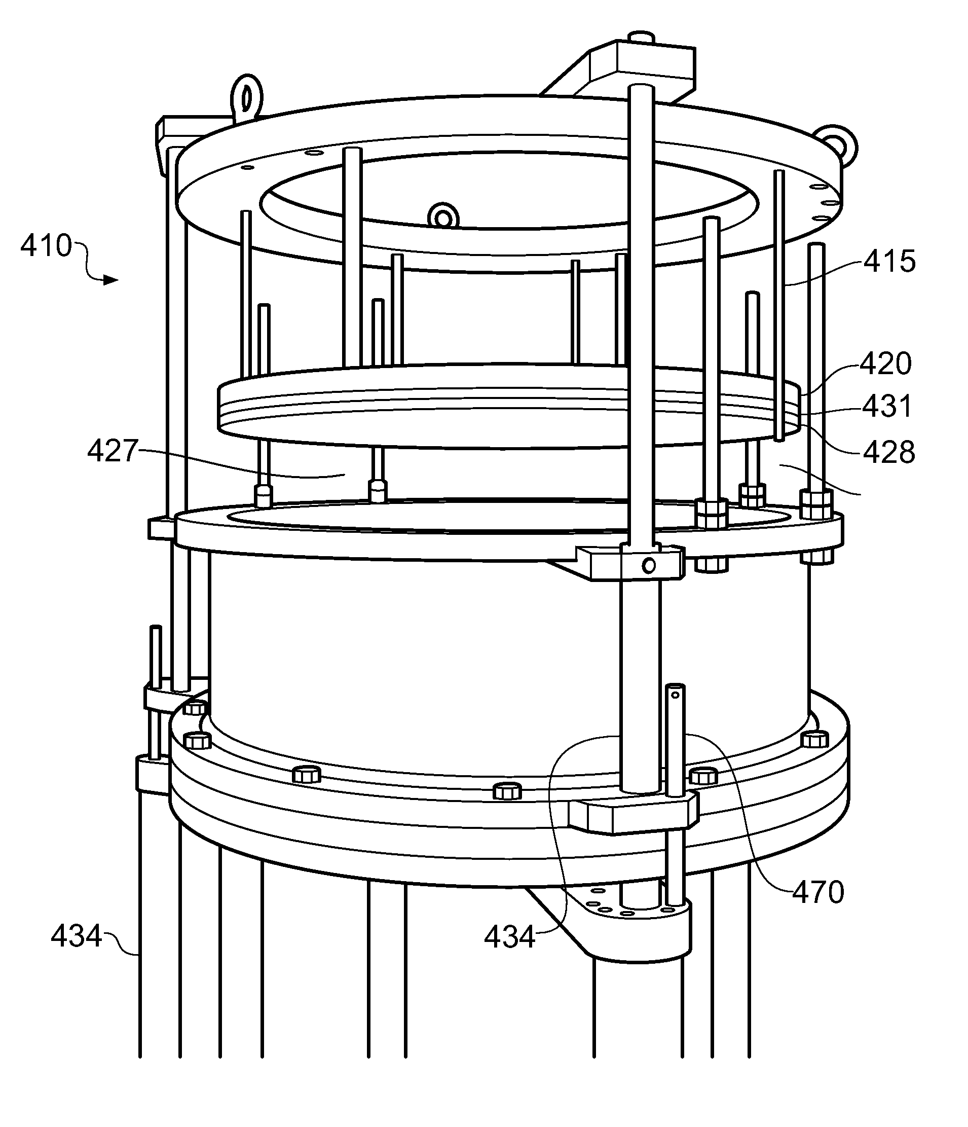
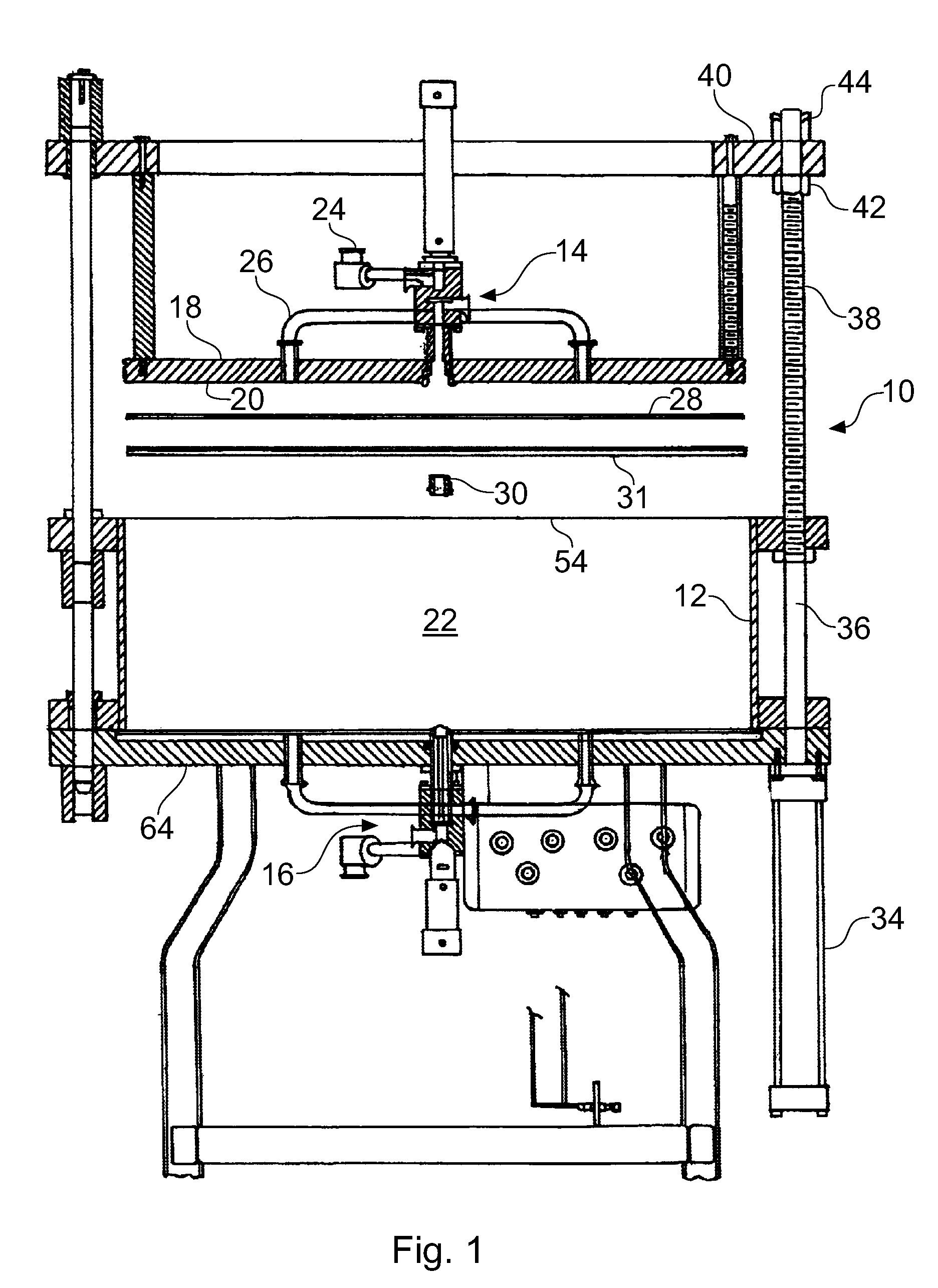
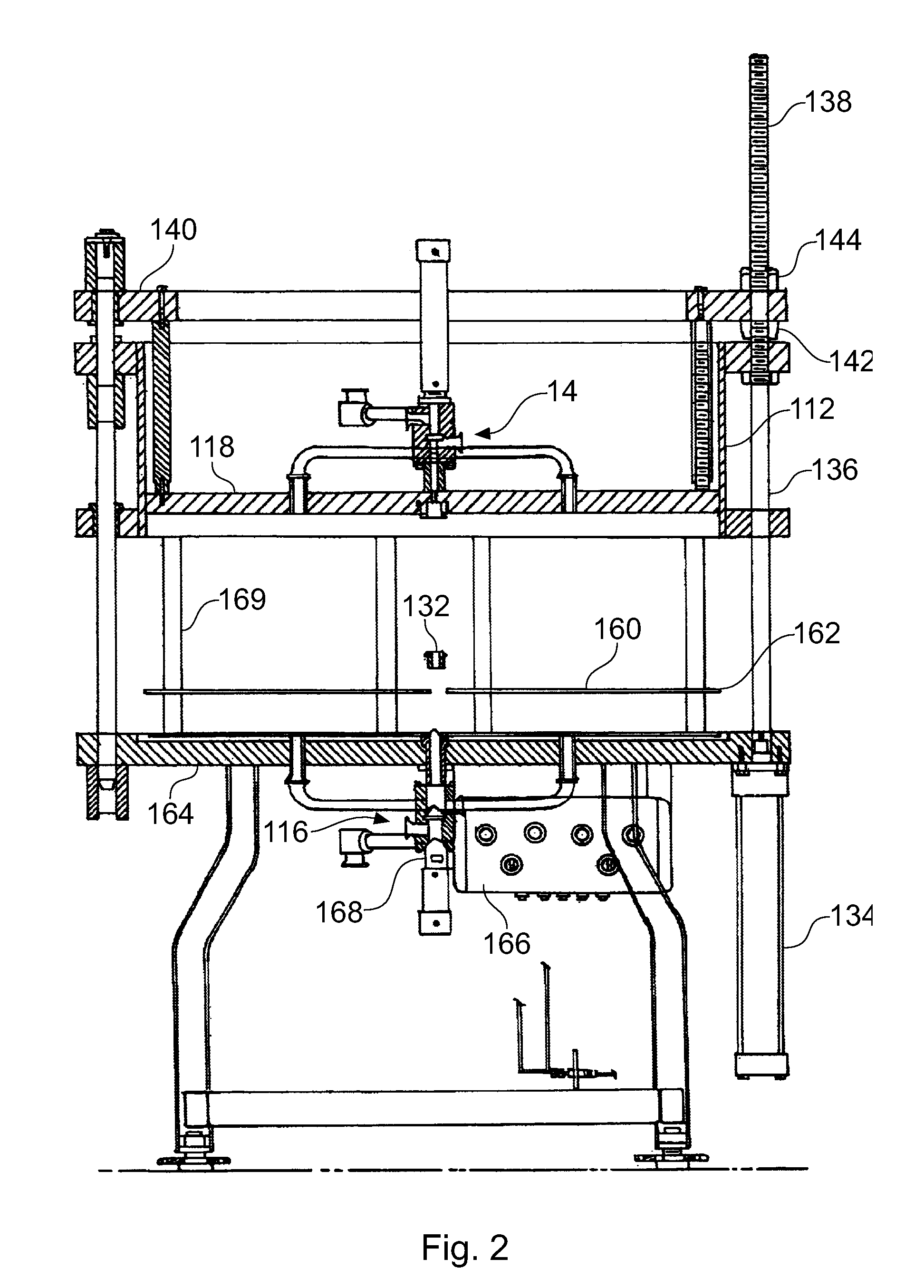
[0084]The present invention is concerned with a method and apparatus for conducting maintenance on a chromatography column. The invention is described by reference to chromatography columns which utilise drive systems to lift and / or lower the adapter assembly, and lift and / or lower the tube and adapter assembly. It will be understood that the invention could equally be described by reference to chromatography columns wherein these components are raised and / or lowered by an overhead hoist or crane. FIG. 1 shows a column 10 known in the art and described in U.S. Pat. No. 6,736,974 which permits maintenance within a chromatography column without the need for a hoist or crane. The column 10 comprises an elongated hollow cylindrical housing 12, or tube, having a dispersion system 14 at the top and a collection system 16 at the bottom. The dispersion system 14 includes a cylindrical drum 18 having an upper cylindrical plunger head or adapter 20 formed at the lower or interior end (i.e. in...


PUM

PropertyMeasurementUnit
angleaaaaaaaaaa
diametersaaaaaaaaaa
fluid-permeable aaaaaaaaaa

Abstract

The present invention relates to methods for conducting maintenance on chromatography columns used in industrial-scale chromatography. In particular, the invention is concerned with safer methods for performing maintenance on such columns, such as cleaning and replacing bed supports, distributors, nozzles, O-rings and other column components, by the use of a handling device to support, lift, carry and manipulate such column components.

Description

CROSS-REFERENCE TO RELATED APPLICATIONS[0001]This application is a contiuation-in-part of allowed U.S. patent application Ser. No. 11 / 763,477 filed Jun. 15, 2007 now U.S. Pat. No. 7,708,891; the entire disclosure of which is incorporated herein by reference in its entirety.FIELD OF THE INVENTION[0002]The present invention relates to methods for conducting maintenance on chromatography columns used in industrial-scale chromatography. In particular, the invention is concerned with safer methods for performing maintenance on such columns, such as cleaning and replacing bed supports, distributors, O-rings and other column components, by the use of a handling device to support, lift, carry and manipulate such column components.BACKGROUND OF THE INVENTION[0003]Chromatography columns may be used in industrial processes to purify process liquids and separate substances of interest from process liquids; typical examples include large-scale preparative purification of fine chemicals and pharm...

Claims


Application Information

Patent Timeline
Patent Type & Authority Patents(United States)
IPC IPC(8): B01D15/08
CPCG01N30/56B23Q3/18B01D15/10B23C3/18
Inventor DAVIS, JOHNERIKSSON, STEFAN K.
Owner CYTIVA SWEDEN AB
Why Eureka
Try Eureka