Noise detection apparatus and method, and noise reduction apparatus and method

a noise reduction and noise detection technology, applied in the field of noise detection apparatus and method, can solve the problems of large change in noise reduction performance, inability to work for noise reduction in moving images, and removal of noise but also minute high-frequency components, so as to accurately detect nois

Active Publication Date: 2010-08-24
RAKUTEN GRP INC
View PDF9 Cites 3 Cited by
  • Summary
  • Abstract
  • Description
  • Claims
  • Application Information

AI Technical Summary

Benefits of technology

[0035]A purpose of the present invention is to provide a noise detection apparatus and a noise detection method that accurately detect noises from a video signal that has noises on images only whereas no noises during the vertical and / or horizontal blanking intervals.
[0036]Another purpose of the present invention is to provide a noise reduction apparatus and a noise reduction method that achieve much improvement in S / N for moving images as well as still images and images with almost no motion and also a high noise reduction performance against varying noise levels.

Problems solved by technology

It is, however, a non-recursive type and hence a relatively larger |Th| in the coring characteristics could inevitably cause that not only noises but also minute high-frequency components are removed, thus improvements in S / N being more or less 3 dB.
In other words, it will not work for noise reduction in moving images.
It is, however, difficult to apply different non-linear attenuation-characteristics modes to the attenuator 216 and gradually change these modes, which could result in a big change in noise reduction performance when the noise level varies.
In other words, they cannot detect noises for a video signal that has noises on images only (even if they are large) whereas carries no noises during the blanking intervals.

Method used


Image

  • Noise detection apparatus and method, and noise reduction apparatus and method
  • Noise detection apparatus and method, and noise reduction apparatus and method
  • Noise detection apparatus and method, and noise reduction apparatus and method

Examples


Embodiment Construction

[0051]Preferred embodiments according to the present invention will be disclosed in detail.

[0052]FIG. 5 shows a block diagram of a preferred embodiment of a noise reduction apparatus according to the present invention.

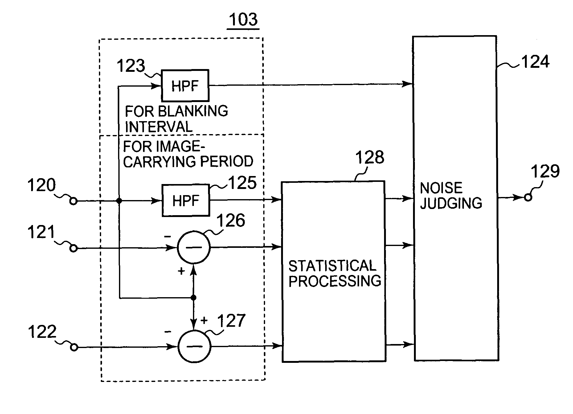
[0053]The noise reduction apparatus shown in FIG. 5 includes a line delay unit 101, an adder 102, a noise detector 103, series-connected mixers 104 and 105, a frame delay unit 107, and a line delay unit 108.

[0054]An input video signal supplied via an input terminal 100 is delayed by one line by the line delay unit 101. The input video signal is further added with an output delayed signal from the line delay unit 108. Noise detection is performed by the noise detector 103 based on the input video signal, a 1-line-delayed video signal from the line delay unit 101, and a 1-frame-delayed video signal from the frame delay unit 107. An output video signal from the mixer 105 is output via an output terminal 106 and also supplied to the frame delay unit 107 and the line delay ...


PUM


Abstract

Four high-frequency components are extracted from video signals: the first from a blanking interval; the second from an image-carrying period between blanking intervals; and the third and fourth from the video and one-line and -frame delayed signals, respectively. Statistical processing is performed to obtain absolute values of the second to fourth component levels per pixel and the number of pixels of the components per image per absolute level. A noise detecting signal is generated based on the first component level irrespective of the processing when the level is higher than a predetermined level, if not, first to third levels are obtained for the first to third components, respectively, each having the smallest number of pixels among levels other than zero each having a larger number of pixels than zero for the components. The detecting signal is generated based upon the lowest or second lowest level among the first to third levels.

Description

CROSS-REFERENCE TO RELATED APPLICATIONS[0001]This application is based on and claims the benefit of priority from the prior Japanese Patent Application No. 2005-219813 filed on Jul. 29, 2005, the entire contents of which are incorporated herein by reference.BACKGROUND OF THE INVENTION[0002]The present invention relates to a noise detection apparatus and a noise detection method for detecting the level of random noises mixed into video signals displayed on a video display apparatus, such as a TV and a monitor screen, and also a noise reduction apparatus and a noise reduction method for reducing such random noises depending on detected noise levels.[0003]Known noise reduction apparatuses employ noise reduction techniques such as coring and recursive filtering.[0004]FIG. 1 shows a block diagram of a known noise reduction apparatus employing coring for noise reduction.[0005]In FIG. 1, a video signal input via an input terminal 200 is supplied to a subtractor 201, a high-pass filter (HPF...

Claims


Application Information

Patent Timeline
Patent Type & Authority Patents(United States)
IPC IPC(8): H04N5/21G06G9/40
CPCH04N5/08H04N5/21H04N5/208
Inventor KUBOTA, KENJI
Owner RAKUTEN GRP INC
Why Eureka
Try Eureka