Supercharge Your Innovation With Domain-Expert AI Agents!

Particle density measuring probe and particle density measuring equipment

a particle density and probe technology, applied in the field of particle density measurement probes and measuring equipment, can solve the problems of inability to accurately measure the radical density in a true plasma atmosphere free the diameter of the tubular body becomes large, and the inability to accurately measure the radical density distribution, etc., to achieve accurate measurement of the spatial distribution of particle densities.

Active Publication Date: 2010-08-24
NU ECO ENG +1
View PDF9 Cites 0 Cited by
  • Summary
  • Abstract
  • Description
  • Claims
  • Application Information

AI Technical Summary

Benefits of technology

[0010]Plasma is an aggregate of neutral particles such as electrons, atomic radicals, molecular radicals, atomic ions, molecular ions; or charged particles. The present invention is directed to a probe and a device for measuring the density in a plasma atmosphere, of particles having a predetermined absorption spectrum characteristic. Therefore, the measurement of densities of atomic radicals, molecular radicals, atomic ions, and molecular ions can be achieved. The present invention is characterized by providing the reflection plate at the front end and arranging the plasma introducing portion for inducting plasma behind the reflection plate, and by causing the main body to propagate light in the axial direction utilizing total reflection. As a result, the diameter of the probe can be reduced to a very small value, and with the probe inserted into the plasma atmosphere, a particle density distribution in the plasma atmosphere can be accurately measured without disturbing the state of plasma.
[0011]A second aspect of the present invention is characterized in that, in the first aspect, the main body of the light guiding member is constituted of a hollow tubular body having a reflection film formed on the inner surface thereof, and guides light in the axial direction using total reflection by the reflection film. In the present invention, the main body is constituted of a tubular body, and is configured to form the reflection film on its inner wall to thereby cause light progress along the axial direction using total reflection by the reflection film. This makes it possible to reduce the diameter of the main body to a small value, and to accurately measure a particle density distribution in a plasma atmosphere without disturbing the state of plasma. The inner diameter of the hollow tubular body is preferably 2 mm or less, and more preferably, 1 mm or less. Since the probe can be formed narrow like this, the particle density can be accurately measured without disturbing the state of plasma. The reflection film is formed by depositing a metal having a high reflectance, such as aluminum, gold, silver, or the like.
[0012]A third aspect of the present invention is characterized in that, in the first aspect, the main body of the light guiding member is an optical fiber comprising a core that guides light and a clad having a refraction index lower than that of the core, and guides light in the axial direction by generating total reflection on the interface between the core and the clad. That is, this aspect is characterized in that the main body is a fiber, and that total reflection is generated on the wall surface of the clad to thereby cause light to progress along the axial direction. This makes it possible to reduce the diameter of the main body to a small value, and to accurately measure a particle density distribution in a plasma atmosphere without disturbing the state of plasma. The diameter of the core of the fiber is preferably 2 mm or less, and more preferably, 1 mm or less. Since the probe can be formed narrow like this, the particle density can be accurately measured without disturbing the state of plasma.
[0015]In this device, a particle density can be measured only by inserting the cylindrical particle density measuring probe from outside the reaction apparatus for generating an atmosphere, into a plasma atmosphere. An optical system other than the particle density measuring probe is disposed outside the reaction apparatus. The use of the particle density measuring probe having a small diameter allows an accurate measurement of the spatial distribution of particle densities without disturbing the state of plasma.
[0016]Since the particle density measuring probe according to the present invention can have a diameter of 2.7 mm or less, and preferably 1.7 mm or less, it is possible to accurately measure a spatial distribution of particle densities without disturbing the state of plasma. In addition, by adjusting the length of the plasma introducing portion along the axial direction, the spatial distribution of particle densities can be measured at a maximum measurement sensitivity.

Problems solved by technology

However, in each of the above-described devices, the tubular body does not guide light, but only performs a function as an enclosure that supports the discharge light source or the reflection plate provided at the front end of the tubular body and that protrudes the hollow portion introducing radicals from outside the reaction apparatus into a plasma atmosphere.
Within the tubular body, a lens and the half mirror exist, which causes a problem that the diameter of the tubular body becomes large, as a matter of course.
Consequently, the tubular body disturbs the state of plasma atmosphere, and has made it impossible to accurately measure a radical density in a true plasma atmosphere free of the tubular body.
In addition, when measuring a radical density distribution within a plasma atmosphere while moving the tubular body, there has been a problem that an accurate radical density distribution cannot be measured since the large tubular body disturbs the state of plasma.

Method used


Image

  • Particle density measuring probe and particle density measuring equipment
  • Particle density measuring probe and particle density measuring equipment
  • Particle density measuring probe and particle density measuring equipment

Examples


first embodiment

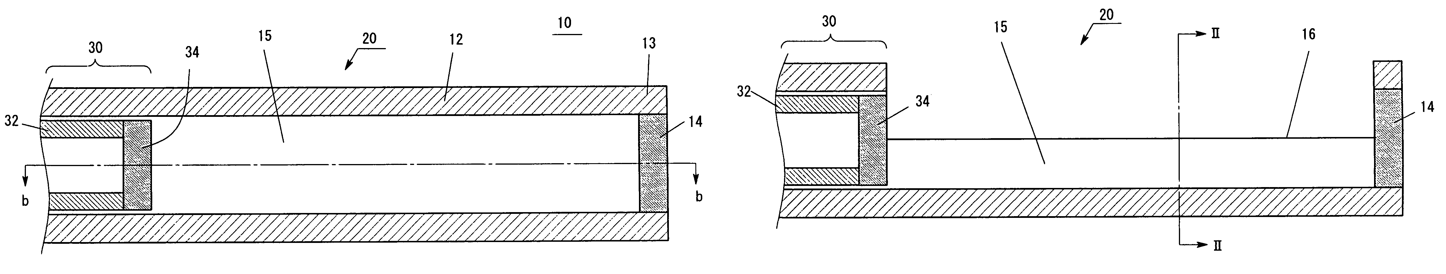
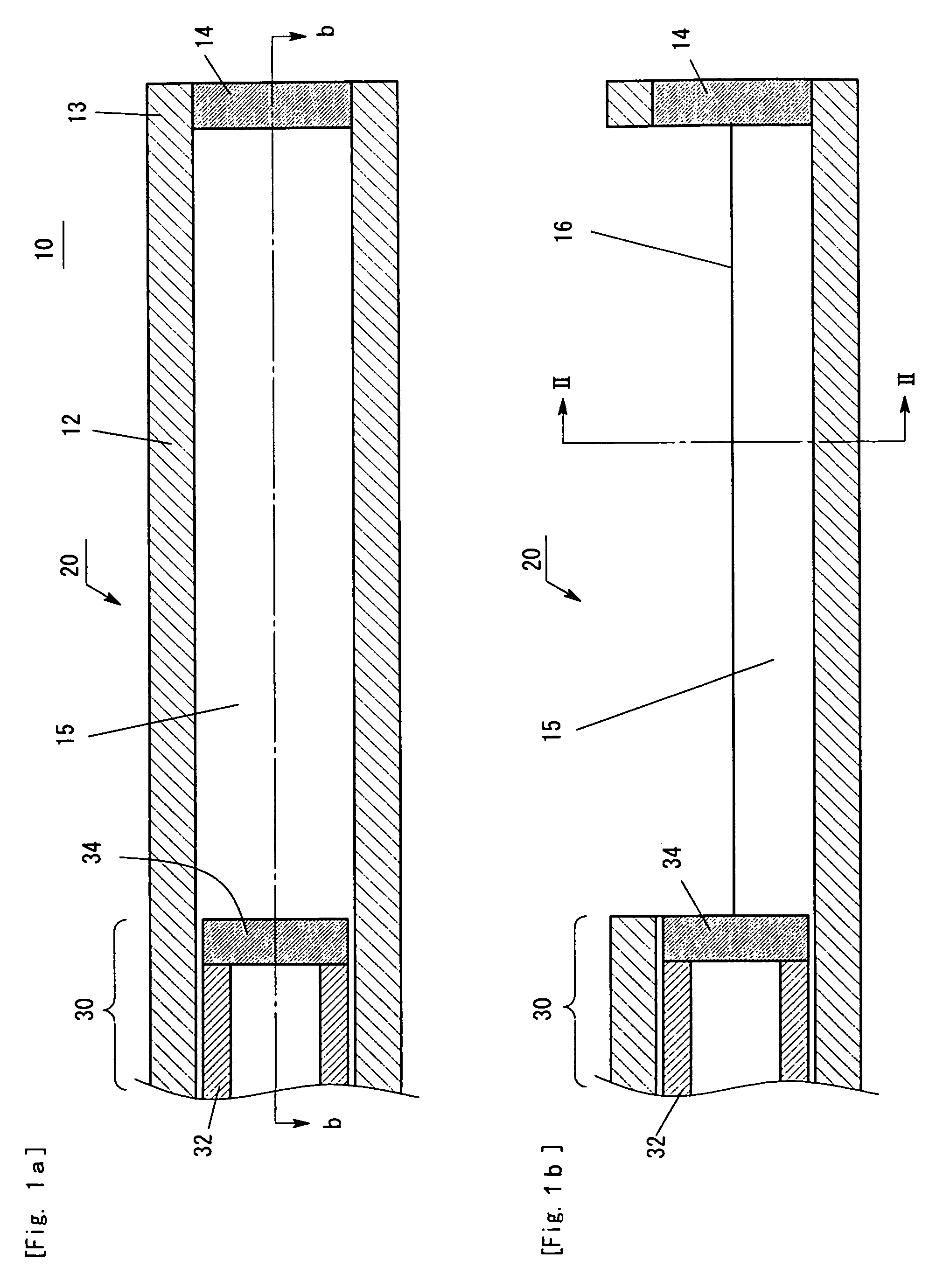
[0031]FIG. 1 shows a particle density measuring probe 10 according to a first embodiment of the present invention. In FIG. 1, (a) is a top view, and (b) is a sectional view taken away along a line b-b in the above top view. A light guiding member 20 comprises: a cylindrical light propagating member 32; a cylindrical support member 12 that covers the outer periphery of the light propagating member 32; a reflection plate 14 provided at the front end of the support member; a plasma introducing portion 15 provided behind the reflection plate 14, for introducing plasma; and a main body 30 located on the light incident side further than the plasma introducing portion 15.

[0032]The cylindrical support member 12 is constituted of a ceramic in order to have a heat resisting property against a plasma atmosphere. Of course, the support member 12 may be constituted of stainless steel. The cylindrical support member 12 has an inner diameter of 1.7 mm, an outer diameter of 2.7 mm, a wall thickness...

second embodiment

[0049]As shown in FIG. 12, the present embodiment constitutes the light propagating member not by a hollow tubular body, but by a glass fiber 80 composed of a core 81 and a clad 82 having a refraction index lower than that of the core 81. This glass fiber 80 is arranged within the support member 12 identical to that in the first embodiment. The constructions of the reflection plate 14 provided at the front end of the support member 12 and the plasma introducing portion 15 provided therebehind is the same as those in the first embodiment. The present glass fiber 80 can be constituted by hard glass in which the outer diameter of the core 81 is 0.7 mm, and that of the clad is 1.1 mm, the wall thickness of the support member 12 is 0.2 mm. Thus, the outer diameter can be made 1.5 mm. The use of this probe also allows the spatial distribution of particle densities to be accurately measured without disturbing the state of plasma.


PUM

PropertyMeasurementUnit
angleaaaaaaaaaa
angleaaaaaaaaaa
inner diameteraaaaaaaaaa

Abstract

Disclosed is a particle density measuring probe for measuring the density of atoms or molecules in a plasma atmosphere by absorption spectroscopy. The probe has a cylindrical light guiding member provided in the plasma atmosphere. At the front end of the light guiding member, there is provided a reflection plate for reflecting light that has propagated through the cylindrical light guiding member. Behind the reflection plate, in a cross section perpendicular to the longitudinal direction of the light guiding member, a part devoid of a portion of wall surface is provided by a predetermined length in the longitudinal direction. A plasma introducing portion allows mutual contact between light passing through this part devoid of a portion of wall surface and atoms or molecules in the plasma atmosphere. The probe has a main body that guides light in an axial direction by total reflection by a side wall, and that is located behind the plasma introducing portion.

Description

BACKGROUND OF THE INVENTION[0001]1. Field of the Invention[0002]The present invention relates to a probe and a measuring device for measuring the density of particles such as atomics, molecules in a plasma atmosphere.[0003]The present invention can be used for accurately measuring the particle density in the plasma atmosphere in order to accurately perform film deposition or etching using a plasma processing device or plasma.[0004]2. Description of the Related Art[0005]When a raw material gas is radicalized to deposit a thin film of a constituent of the gas on a processing target or to etch the processing target, in order to accurately control these processings, it is necessary to measure the density of atoms such as radicals in a plasma atmosphere to thereby control the generation of plasma. For this purpose, light is applied to a plasma atmosphere, and an atomic density is measured based on the absorption characteristic of this light.[0006]As a device for measuring the atomic dens...

Claims


Application Information

Patent Timeline
Patent Type & Authority Patents(United States)
IPC IPC(8): G01N21/00H05B31/26G01B9/02G01J3/45H01J7/24
CPCG01N21/15G01N21/68H05H1/0037
Inventor HORI, MASANUTAKASHIMA, SEIGOKANO, HIROYUKIDEN, SHOJI
Owner NU ECO ENG
Features
  • R&D
  • Intellectual Property
  • Life Sciences
  • Materials
  • Tech Scout
  • Unparalleled Data Quality
  • Higher Quality Content
  • 60% Fewer Hallucinations
Learn More