Lead for AV nodal vagal stimulation through an epicardial fat pad

a nodal vagal and epicardial technology, applied in the direction of epicardial electrodes, internal electrodes, therapy, etc., can solve the problem of not being designed for defibrillation of the hear

Inactive Publication Date: 2010-08-24
THE CLEVELAND CLINIC FOUND +1
View PDF7 Cites 6 Cited by
  • Summary
  • Abstract
  • Description
  • Claims
  • Application Information

AI Technical Summary

Benefits of technology

[0008]A medical electrical lead for conducting electrical signals between an electrical stimulator and a heart site includes a lead body extending from a distal non-conductive disk member to a proximal connector for attachment to the stimulator, first and second spaced electrodes protruding from the disk member for puncturing engagement with the epicardial surface of the heart in the region of an AVN fat pad containing ganglia which extend to the AV node providing an electrical connection between the atrium and the ventricle, a first conductor extending from the first electrode to a first terminal of the connector, and a second conductor extending from the second electrode to a second terminal of the connector such that electrical current from the electrical stimulator is caused to flow through the ganglia between the first and second electrodes to stimulate the AV node to control ventricular rate in the presence of atrial fibrillation.
[0012]Another lead configuration provides for an increased surface area on each pole. This increase surface area is in the form of a plate like surface located intermediate the two anode pins and the two cathode pins. This plate like surface can also have a curved shape so as to improve the tissue contact achieved by that electrode.
[0015]Still another feature of the present invention is the provision of such a novel technique and lead which provides the ability to control the ventricular rate of the heart through the AV node from the fat pad region of the heart.

Problems solved by technology

The lead in this configuration is not designed for defibrillation of the heart.

Method used


Image

  • Lead for AV nodal vagal stimulation through an epicardial fat pad
  • Lead for AV nodal vagal stimulation through an epicardial fat pad
  • Lead for AV nodal vagal stimulation through an epicardial fat pad

Examples


Embodiment Construction

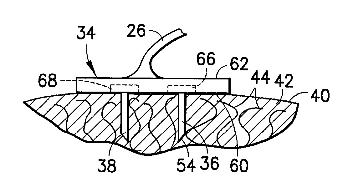
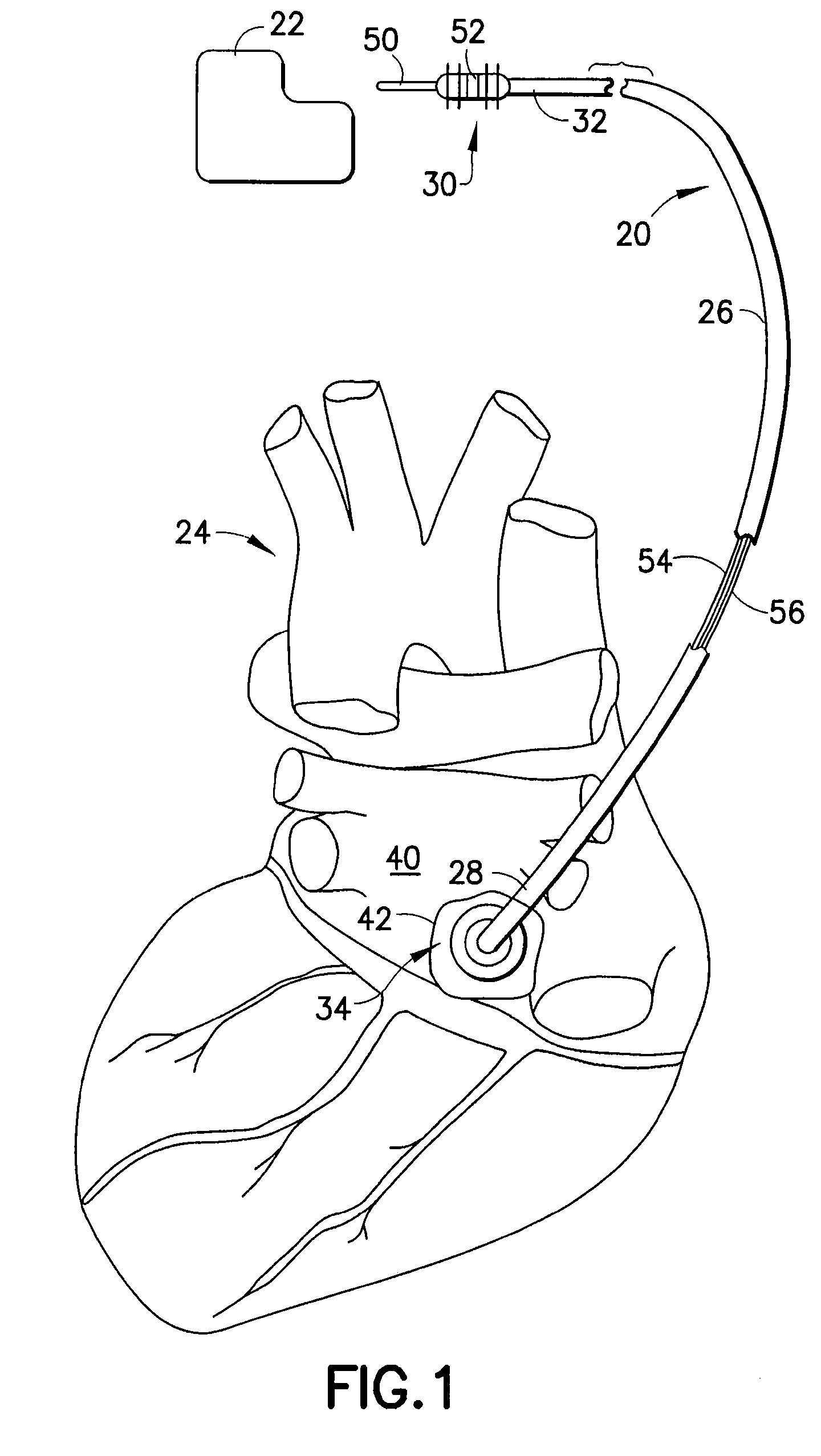
[0029]Refer now to the drawings and, initially, to FIG. 1 in which is shown a diagrammatic perspective view of a medical electrical epicardial lead 20 incorporating features of the present invention for use in association with an electrical stimulator 22 such as a pacemaker or defibrillator providing electrical stimulation to a heart 24. Although the present invention will be described with reference to the embodiments shown in the drawings, it should be understood that the present invention can be embodied in many alternate forms or embodiments. In addition, any suitable size, shape or type of elements or materials could be used.

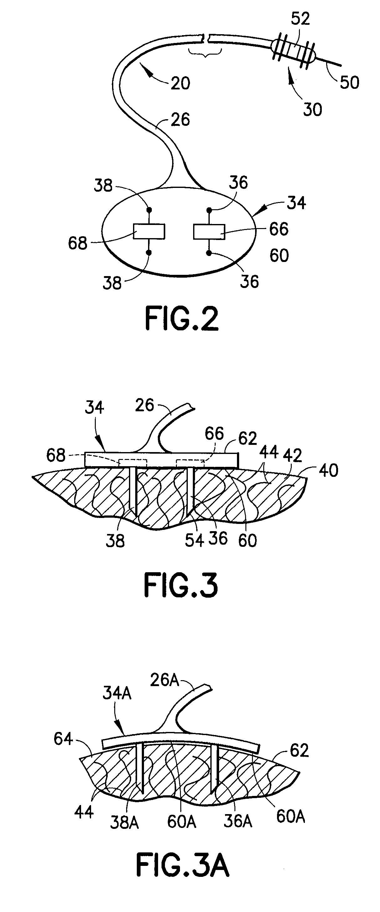
[0030]The lead 20 is adapted to conduct electrical stimulation from the electrical stimulator 22, which may be, alternatively and selectively, implantable or external to a site of the heart 24 and to conduct electrical signals of the heart from the site to the stimulator. The lead 20 includes an elongated lead body 26 extending from a lead body distal end 2...


PUM


Abstract

A medical electrical lead for conducting electrical signals between an electrical stimulator and a heart site includes a lead body extending from a distal non-conductive disk member to a proximal connector for attachment to the stimulator, first and second spaced electrodes protruding from the disk member for puncturing engagement with the epicardial surface of the heart in the region of an AVN fat pad containing ganglia which extend to the AV node providing an electrical connection between the atrium and the ventricle, a first conductor extending from the first electrode to a first terminal of the connector, and a second conductor extending from the second electrode to a second terminal of the connector such that electrical current from the electrical stimulator is caused to flow through the ganglia between the first and second electrodes to stimulate the AV node to control ventricular rate in the presence of atrial fibrillation.

Description

TECHNICAL FIELD[0001]The present invention generally relates to stimulation leads for use with implantable cardiac stimulation devices and, more particularly, to a technique and lead for controlling ventricular rate in the presence of atrial fibrillation.BACKGROUND[0002]A patient who is suffering from atrial fibrillation can experience a ventricular rate (bpm) that is higher than normal for that patient. This can result in adverse effects of left ventricular function. Some examples of these effects are diminished preload and contractility of the chambers due to shorter filling intervals. Atrial fibrillation (AF) is recognized as the most common clinically significant cardiac arrhythmia. Current data estimated that 2.3 million Americans have AF. Because the prevalence of AF increases with age and because of the aging population, the number of AF patients is estimated to increase 2.5-fold during the next 50 years.[0003]Currently, there are two broad strategic treatment options for AF:...

Claims


Application Information

Patent Timeline
Patent Type & Authority Patents(United States)
IPC IPC(8): A61N1/05
CPCA61N1/0587A61N1/3621
Inventor MORGAN, KEVIN L.MAZGALEV, TODOR N.
Owner THE CLEVELAND CLINIC FOUND
Why Eureka
Try Eureka