
Interior trim member of work vehicle and method of manufacturing the same

a technology for interior trim and work vehicles, which is applied in the field of interior trim members, can solve the problems of inability to easily remove inability to insert the front dash panel forward anymore, and inability to secure the front dash panel, etc., and achieves the effect of secure elastic deformation, easy attachment and detachment of the interior trim member, and easy detachmen

Inactive Publication Date: 2010-08-31
KOMATSU LTD
View PDF22 Cites 13 Cited by
  • Summary
  • Abstract
  • Description
  • Claims
  • Application Information

AI Technical Summary

Benefits of technology

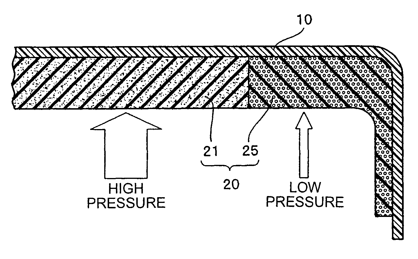
[0025]The periphery including the concave notch portion fitted while interfering with the interference body is constructed by the cushion body made of the elastically deformable material, and the structure member made of the material which is light and harder than the cushion body is arranged in the other region than the region in which the cushion body is arranged in the interior trim member so as to be integrated. This makes it possible to easily attach and detach the interior trim member over the interference body by elastically deforming the portion of the cushion body near the concave notch portion, at a time of attaching and detaching the interior trim member to the incorporated position or from the incorporated position. Since each of the cushion body and the structure member at this time is provided with the hardness mentioned above, it is possible to securely achieve an elastic deformation and return of the portion of the cushion body, and it is possible to easily attach and detach the interior trim member while maintaining the original shape of the interior trim member. Further, since the cushion body and the structure member are covered and integrated by the same skin member, an excellent peeling strength is achieved, the cushion body and the structure member are not broken even by carrying out a repeated attaching and detaching operation, and an outer appearance can be long maintained.
[0026]In the case that the cushion body is integrated with a part of the structure member and the skin member by the foaming, a peeling strength becomes high. Particularly, if the skin member is formed by a soft or semi-hard urethane resin, a fiber or the like, the cushion body is structured by a semi-hard urethane foamed body, and the structure member is structured by a foamed body such as a hard urethane or the like, an adhesion force is increased because the skin member, the cushion body and the structure member have an affinity with each other, and the peeling strength is further improved. At this time, the hardness of the cushion body and the structure member can be optionally changed within the range of the hardness mentioned above on the basis of a role of the interior member. Further, a material obtained by a sheet metal working is generally used in the driver seat or the like to which this kind of interior trim member is installed. Even if a dimensional tolerance on a manufacturing appears to some extent, a dispersion thereof is efficiently reduced by an elasticity of the cushion body. In addition, the cushion layer can be interposed in a whole of the interior member. In this case, a step is not generated in a boundary portion with respect to a single region of the cushion body, and a glossy outer appearance can be obtained.
[0027]The interior trim member in accordance with the present invention having the structure mentioned above can be efficiently and easily manufactured by the manufacturing method mentioned above in accordance with the present invention. Since the interior trim member in accordance with the present invention is having the structure mentioned above, there is left the space for forming the cushion body in the mold at the final forming time. The skin member and the structure member are integrally formed by arranging the skin member along the cavity of the lower mold in a close contact manner, arranging the structure member made of the thermosetting resin material corresponding to the hard material being light and having the rigidity in the region which is not interfered with the interference body existing at the incorporated position at a time of inserting, at least in one side edge portion which is orthogonal to the inserting direction to the incorporated position of the interior trim member in the cavity of the upper mold, and thereafter filling the cushion member within the space formed between the mold having the upper mold and the lower mold at a time of closing the mold, and the skin member and the structure member.
[0028]At a time of filling the cushion member in the space, two methods are provided in accordance with the present invention. One of them is to set the skin member to the lower mold, and thereafter vacuum suck so as to deform the skin member along a whole shape of the lower mold. Next, the structure member is integrally formed in the skin member by moving down the upper mold so as to close the mold, and injecting the thermosetting resin material of the structure member. The cavity of the upper mold at this time is formed in the region except the filling space of the cushion member. For example, an insertion mold is inserted to the filling space of the cushion except the region at a time of forming the structure member. After finishing the formation of the structure member, three elements are integrated by detaching the insertion mold inserted to the filling space of the cushion member, and introducing the cushion member to the cushion member filling space formed there so as to foam. The interior trim member manufactured at this time is structured such that the elastically deformable cushion body including the portion near the concave notch portion is integrally formed in the side surface of the structure member made of the hard resin, and the skin member is directly coated over a whole of the surface of the structure member and the cushion body so as to be integrated.
[0029]According to the other, the structure member is previously formed, and the skin member and the structure member are respectively arranged in the lower mold and the upper mold at a time of closing the mold. The region forming the cushion body at this time is left so as to be mounted and fixed to the lower mold, and the skin member is vacuumed along the cavity of the upper mold so as to be held in the upper mold. If the mold is closed by moving down the upper mold in this state, the cavities of the upper mold and the lower mold are formed in such a manner that a desired gap is formed between the skin member and the structure member. If the mold is closed, the foamed resin is introduced into the gap and the left space, and the space is filled and formed by the foamed body, whereby three elements are integrated. It is preferable to use the semi-hard polyurethane which can be directly foamed on the spot, for the foaming at this time. Alternatively, it is possible to use a thermoplastic elastomer resin to which a foaming agent is added, as the cushion member. Further, it is preferable to use the hard polyurethane foamed body which is light and is rich in a heat insulating property, for the structure member.

Problems solved by technology

Accordingly, since a space for installing a front dash panel is expanded little by little from an upper portion toward a lower side, it is unavoidable to install the front dash panel in such a manner as to intrude horizontally toward a front side.
Accordingly, the post forms an interference body, and is interfered with the corner portions in the driver side of the right and left wing portions, and it is impossible to insert the front dash panel forward anymore.
Further, if the front dash panel is once fitted by using any means, the front dash panel can not be easily detached, even in the case that it is intended to detach the front dash panel, for example, for replacing or repairing the instruments and gauges.

Method used


Image

  • Interior trim member of work vehicle and method of manufacturing the same
  • Interior trim member of work vehicle and method of manufacturing the same
  • Interior trim member of work vehicle and method of manufacturing the same

Examples


Embodiment Construction

[0084]A description will be given specifically of typical embodiments in accordance with the present invention with reference to the accompanying drawings.

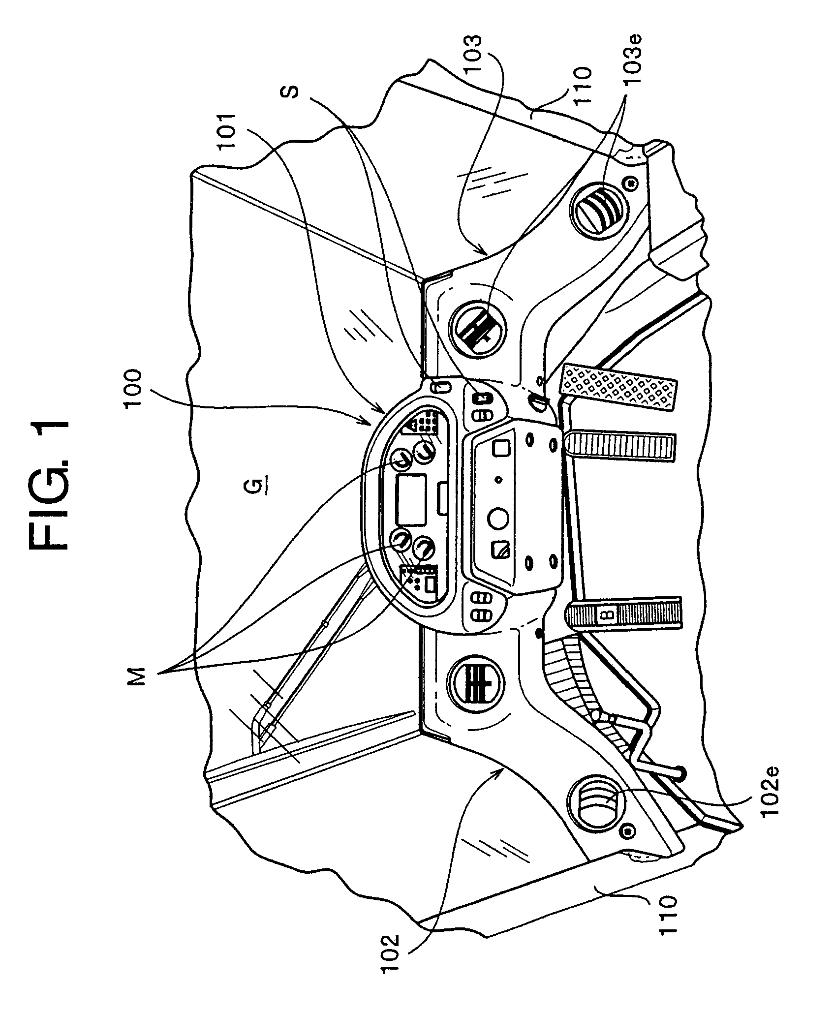
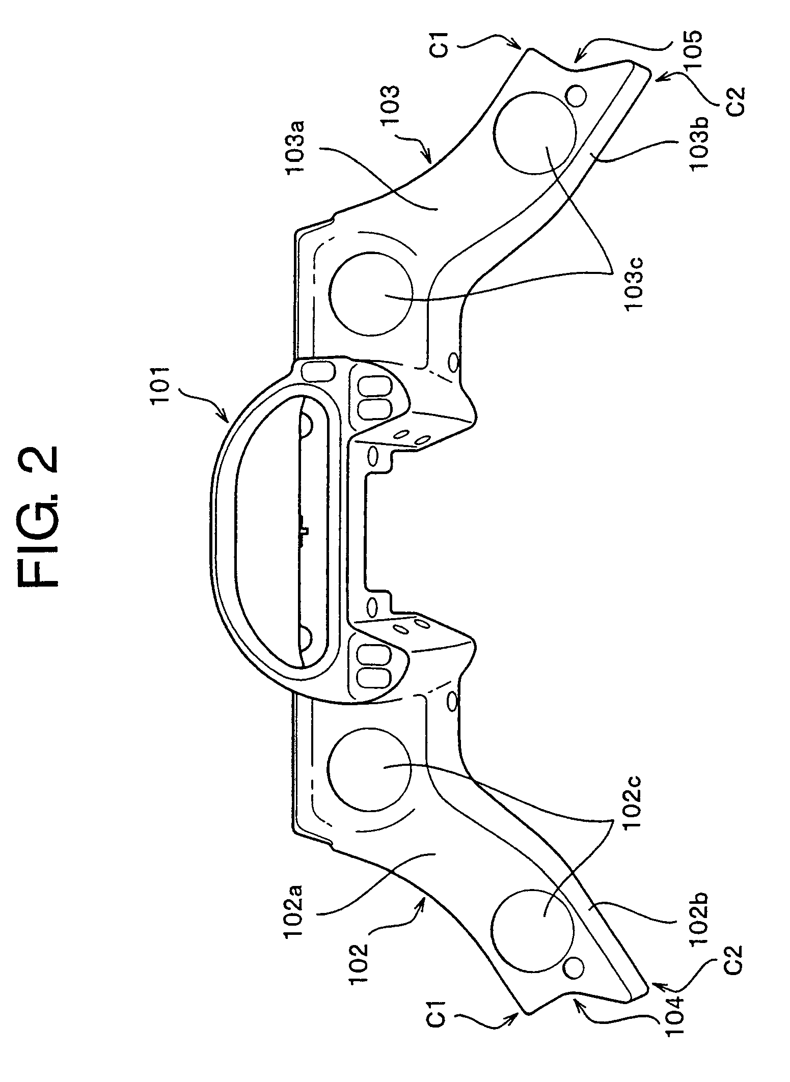
[0085]FIG. 1 shows an outer appearance at a time of viewing a part of a passenger cabin in which a dash board 100 corresponding to an interior trim member is installed to a front side of a driver seat of a wheel load in accordance with a first embodiment of the present invention. As is understood from the drawing, an instruments and gauges arranging portion 101 to which various instruments and gauges M and switches S are attached is arranged in a center portion of the dash board 100, and there are provided left and right wing portions 102 and 103 extending to a diagonally near side while expanding a gap from both left and right side ends. The instruments and gauges arranging portion 101 is formed as a horizontally C-shaped form, and the instruments and gauges M are fitted and fixed to a center thereof while being tilted to a front...


PUM

PropertyMeasurementUnit
bending strengthaaaaaaaaaa
thicknessaaaaaaaaaa

Abstract

A concave notch portion to which an interference body is fitted is formed in an interference region with the interference body existing in an incorporated portion of at least one side edge portion of an interior trim member. A cushion body made of an elastically deformable material is arranged in a periphery including the concave notch portion, and a structure member made of a material which is light and harder than the cushion body is arranged in the other region than the arranged region of the cushion body in the interior trim member. The skin member, the structure member and the cushion body are integrated by a molding. Consequently, an interior trim member is removable from an incorporated position, even in the case that a post exists in a driver seat, in the rigid interior trim member incorporated in the driver seat of various work vehicle.

Description

CROSS-REFERENCE TO RELATED APPLICATIONS[0001]This application is a 371(c) National Phase of International patent application Serial No. PCT / JP2006 / 318184 filed Sep. 13, 2006 which claims priority to Japanese patent application Serial No. 2005-274424 filed Sep. 21, 2005, the entire disclosures of which are incorporated herein in their entireties.TECHNICAL FIELD[0002]The present invention relates to an interior trim member such as an instrument panel, a dash board or the like installed in a driver's cabin of a vehicle for various works, for example, a construction, a civil engineering and the like, or a work vehicle such as a dump truck, a fork lift, a farm machine or the like, and a method of manufacturing the same, and more particularly to an interior trim member which can be easily incorporated or detached under a state in which an interference body constituted by a rigid body such as a column or the like is arranged at an incorporated position of the interior trim member so as to ...

Claims


Application Information

Patent Timeline
Patent Type & Authority Patents(United States)
IPC IPC(8): B60R13/02
CPCB29C33/18B29C39/10B29C39/42B29C44/086B29C44/146B29C45/1635B29C45/1676B60R13/0256B29C2033/0094B29K2105/04B29L2031/58
Inventor SATO, KAN'ICHI
Owner KOMATSU LTD
Learn More