Method and apparatus for producing a discrete droplet for subsequent analysis or manipulation

a technology of discrete droplets and droplets, which is applied in the direction of biochemistry apparatus and processes, separation processes, particle separator tubes, etc., can solve the problems of large molecules of biological origin such as proteins, peptides and strands of dna and rna, and the inability to identify proteins that are expressed at low levels. , the problem of 0.01% or less of the sample material is used, and the difficulty of ionizing large molecules of biological origin

Inactive Publication Date: 2010-08-31
SIMON FRASER UNIVERSITY
View PDF13 Cites 24 Cited by
  • Summary
  • Abstract
  • Description
  • Claims
  • Application Information

AI Technical Summary

Problems solved by technology

Ionizing large molecules of biological origins such as proteins, peptides and strands of DNA and RNA has proven difficult in the past since these molecules have effectively zero vapour pressure and are labile.
A challenge in protein measurement, however, is sensitivity since there are estimated to be approximately 100,000 distinctly different proteins in any one cell.
Even in these situations, however, the proteins that are expressed at low levels are generally not identified because their numbers are below the level of detection.
A disadvantage of the ESI method is that only a small fraction (0.01% or less) of the sample material is utilized.
The reason for this is that the electric field that disperses the liquid solution into droplets is also responsible for causing detrimental space charge effects.
Hence, the overall sample utilization efficiency is low in conventional ESI methods because the droplets / ions at atmospheric pressure are extremely difficult to focus through the sampling orifice.
This limits the effectiveness of ESI if only a small amount of analyte is available for analysis, which is often the case in respect of bio-molecules.
The matrix absorbs the energy from the laser, causing rapid vibrational excitation and desorption of the chromophore.
As has been pointed out, however, handling of volumes of picoliters becomes problematic in smaller inner diameter capillaries because of the higher surface to volume ratio that leads to stronger tension forces.

Method used


Image

  • Method and apparatus for producing a discrete droplet for subsequent analysis or manipulation
  • Method and apparatus for producing a discrete droplet for subsequent analysis or manipulation
  • Method and apparatus for producing a discrete droplet for subsequent analysis or manipulation

Examples


example 2-6

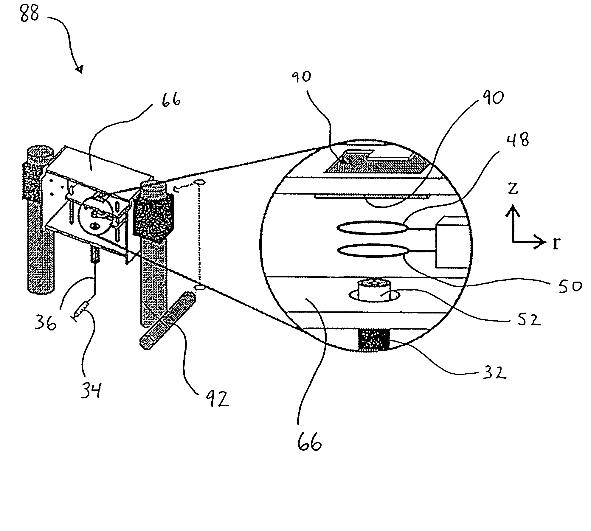
[0117]Examples 2-6 relate to the use of droplet generator 32 and levitation device 30 to deposit sample onto a MALDI plate 90 for subsequent mass spectrometry.

[0118]The following apply for each of Examples 2-6:[0119](a) an apparatus substantially the same as the apparatus 88 of FIG. 10 was used to generate droplets, induce a net charge thereon, levitate the droplets in the electrodynamic balance and deposit the droplets onto MALDI plates. In one instance, the droplets were deposited onto a MALDI plate pre-coated with matrix, while in another instance, the matrix was added directly to the starting solution and the plates were not matrix pre-coated;[0120](b) following droplet deposition, the MALDI plates were removed from the electrodynamic balance chamber and analyzed using a Perseptive Biosystems Voyager-DE MALDI-TOF-MS;[0121](c) the analytes used were Chenodeoxycholic acid diacetate methyl ester and leucine enkephalin, while the matrix was α-cyano-4-hydroxycinnamic acid (HCCA). NaC...

example 2

[0125]FIGS. 12A, 12B and 12C are photographs (magnification 5×) illustrating, in sequence, the levitation of charged droplets within the electrodynamic balance 30, and the ejection of a single droplet from within the electrodynamic balance 30. The photographs were acquired with a digital camera focused through a single microscope objective lens. The motion of a levitated droplet was at 60 Hz, the same frequency as the AC waveform applied to the ring electrodes of the electrodynamic balance. The frequency of oscillation of the droplet's trajectory was faster than the shutter speed of the camera, thus the droplets levitated in the electrodynamic balance appear in FIGS. 12A-12C as lines.

[0126]In the sequence from FIGS. 12A to 12C, the DC potential applied to the induction electrode (+125 V) and the AC trapping potential (1150 V0-p) were held constant while the DC potential applied to the MALDI plate was increased from +150 V to +300 V. FIG. 12A represents a DC potential of +150 V appli...

example 3

[0128]FIGS. 13A and 13B illustrate the results of different approaches for deposition of particles onto a MALDI plate 90. The photographs of FIGS. 13A and 13B were acquired by focusing a digital camera through a microscope. The magnification of FIG. 13A is 20× and the magnification of FIG. 13B is 25×. The number “45” appearing in FIGS. 13A and 13B was etched into the MALDI plate by the manufacturer.

[0129]FIG. 13A is a photograph of a MALDI plate 90, pre-coated in matrix 100, after the deposition of seven droplets 102 (circled for illustration purposes) simultaneously (or near simultaneously) ejected from the electrodynamic balance 30. Simultaneous ejection of the particles occured with the application of a single large potential pulse. In the case of FIG. 13A, the single pulse applied to the MALDI plate 90 was +850 V. This caused near instantaneous removal of the droplets 102 from the electrodynamic balance 30. In doing so, the relative positions of the levitated droplets at the ins...


PUM

PropertyMeasurementUnit
voltageaaaaaaaaaa
diameteraaaaaaaaaa
timeaaaaaaaaaa

Abstract

A method and apparatus for producing a discrete particle for subsequent analysis (such as mass spectrometry) or manipulation is disclosed. A discrete particle is generated by a particle generator. A net charge is induced onto the particle by an induction electrode. The particle is delivered to a levitation device where it is then electrodynamically levitated. If the particle is a droplet, desolvation will occur, leading to Coloumbic fissioning of the droplet into smaller droplets. The movement of the levitated droplet(s) can be manipulated by an electrode assembly. The droplet(s), and the charge thereon, can be delivered to a mass spectrometer in one aspect of the invention, providing an ion source for mass spectrometry without the detrimental space charge effects of electrospray ionization techniques. In another aspect of the invention, the levitated particle(s) may be controllably and precisely deposited onto a plate for subsequent analysis by matrix assisted laser desorption and ionization mass spectrometry.

Description

REFERENCE TO RELATED APPLICATION[0001]This application claims the benefit of U.S. provisional application Ser. No. 60 / 242,058 filed Oct. 23, 2000.TECHNICAL FIELD[0002]This invention pertains to the production of a discrete particle for application, for example, in the field of mass spectrometry.BACKGROUND[0003]Mass spectrometry is a technique that weighs individual molecules, thus providing valuable chemical information. A mass spectrometer operates by exerting forces on charged particles (ions) in a vacuum using magnetic and electric fields. A compound must be charged (ionized) to be analyzed in a mass spectrometer. The ions must be introduced in the gas phase into the vacuum of the mass spectrometer. Ionizing large molecules of biological origins such as proteins, peptides and strands of DNA and RNA has proven difficult in the past since these molecules have effectively zero vapour pressure and are labile. A major thrust in mass spectrometry for some time has been the development ...

Claims


Application Information

Patent Timeline
Patent Type & Authority Patents(United States)
IPC IPC(8): G01N24/00G01N27/62G21K1/00G21K1/087H01J49/04H01J49/06H01J49/10H05H3/04
CPCH01J49/04H05H3/04Y10T436/24
Inventor AGNES, GEORGEFENG, XIAOBOGAN, MICHAEL
Owner SIMON FRASER UNIVERSITY
Why Eureka
Try Eureka