

Controllable synthesis of porous carbon spheres, and electrochemical applications thereof
A porous carbon and spherical technology, applied in the field of preparation of the porous carbon, can solve the problems of ignoring the macroscopic shape
- Summary
- Abstract
- Description
- Claims
- Application Information
AI Technical Summary
Problems solved by technology
Method used
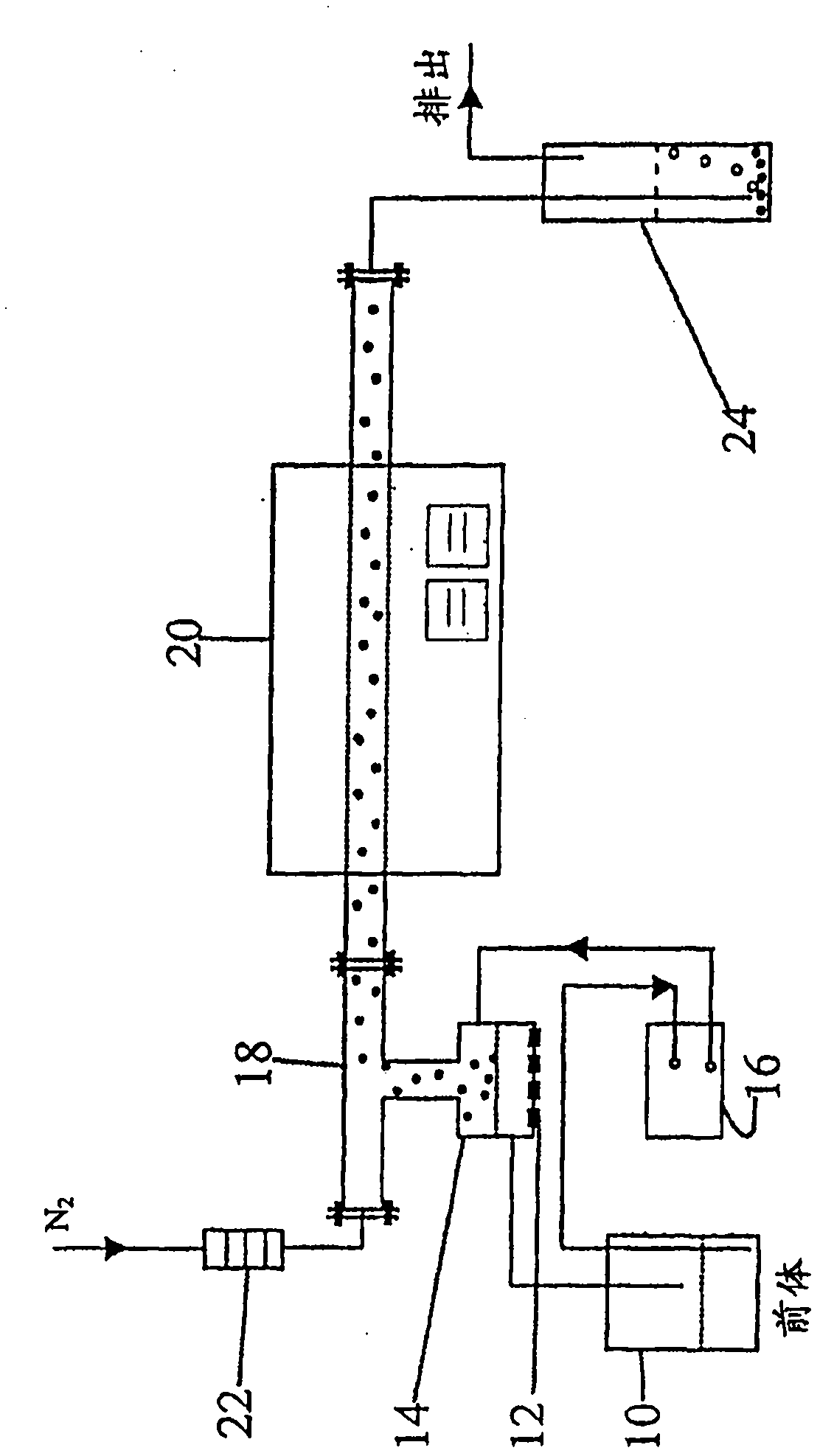
Image

Examples
Embodiment 1
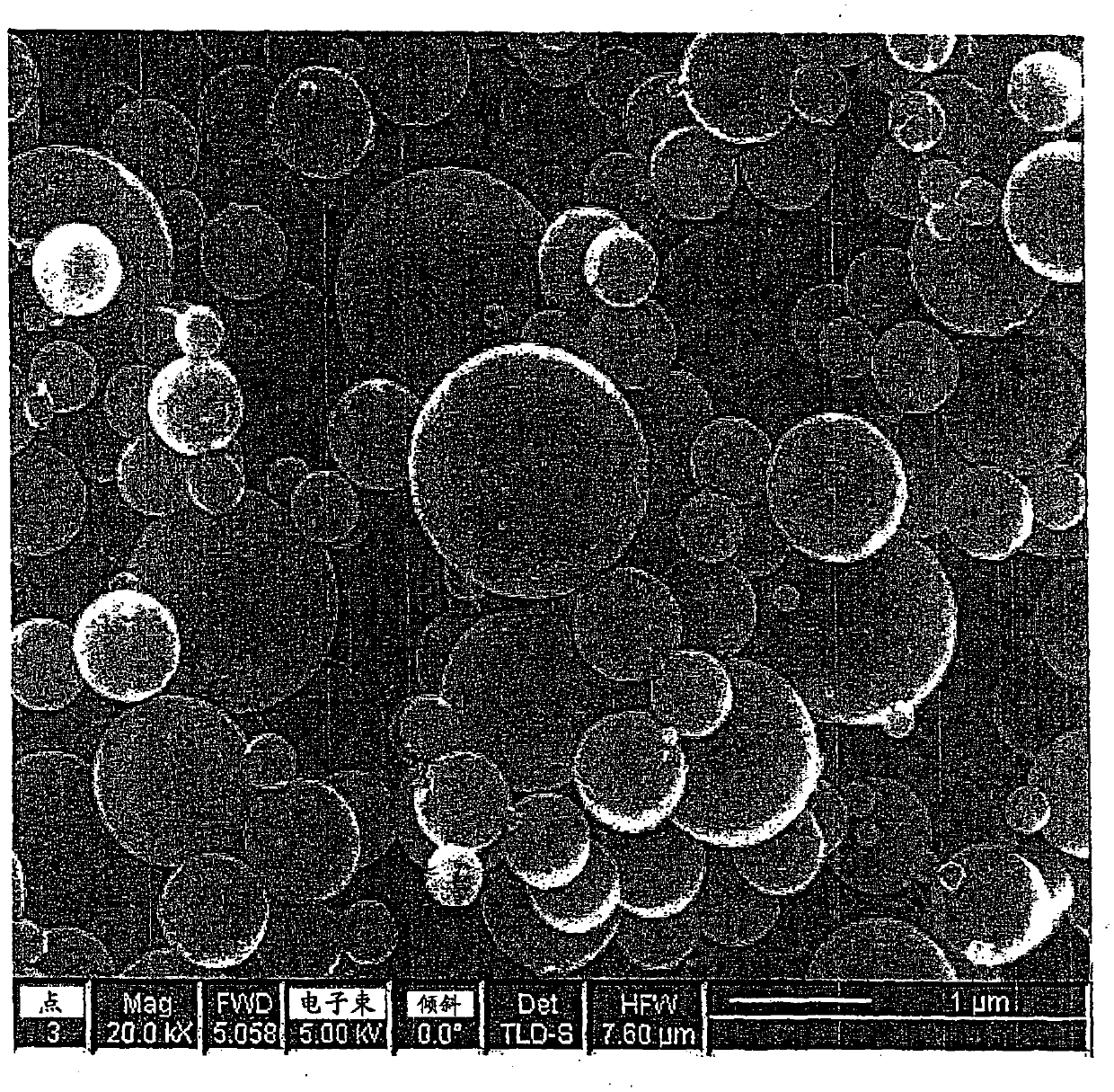
[0060] In this example, porous carbon spheres were synthesized through a 22 nm colloidal silica template according to the method detailed above. In this case, sucrose was used as the carbon source with a silicon oxide to carbon weight ratio of 2:1.
[0061] Figure 2a SEM pictures of carbon-silica composite particles synthesized by 22nm colloidal silica template are shown. Composite particles have a complete spherical shape and a smooth surface.
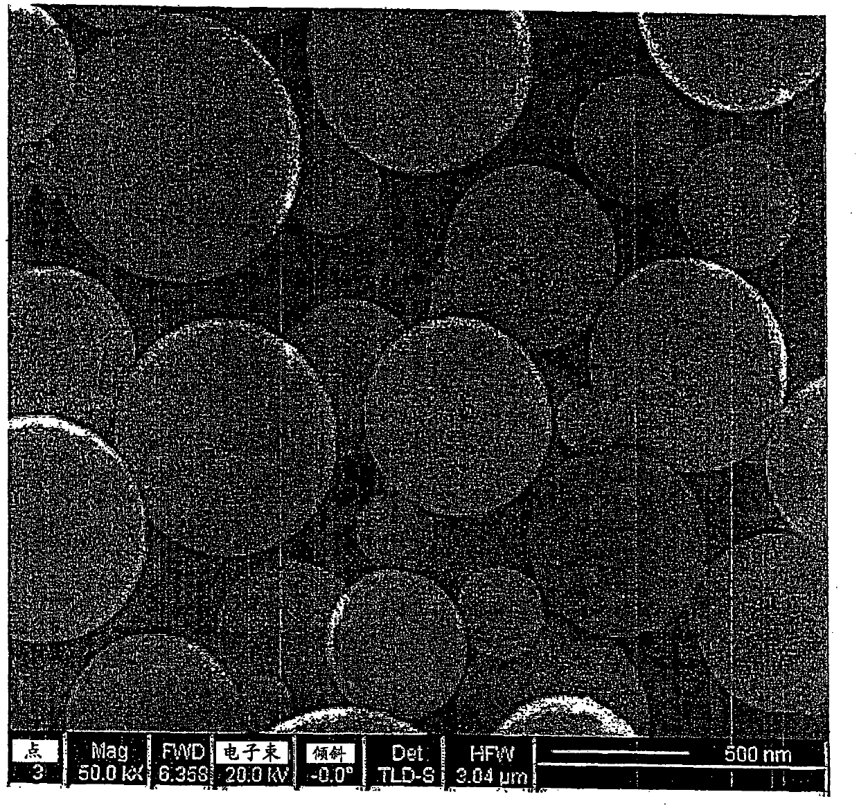
[0062] Figure 2b SEM pictures of carbon spheres after etching silicon oxide are shown. Figure 2c is a magnified photograph of a single carbon sphere. It is clear that the etching process does not destroy the spherical shape of the primary particles. The silicon oxide inclusions are etched from the carbon matrix, which results in honeycomb carbon spheres with many uniform nanometer-sized pores. TEM photograph of a single carbon sphere ( Figure 2d ) shows that the carbon spheres are hollow. Such as image 3 As shown in , th...
Embodiment 2
[0066] To improve the stability of such open framework carbon structures, graphitic carbon sphere structures were introduced by adding a catalytic graphitization step to the procedure described in Example 1. Add transition metal ions such as Fe, Co, Ni or others in the form of salts (chloride, sulfate, nitrate, acetate, etc.) to the precursor solution, and the metal / carbon source weight ratio is from 1:20 to 1:5. The metal or metal oxide nanoparticles derived from the salt decomposition product are used as a catalyst in step (3) to graphitize the porous carbon spheres. Figure 6XRD patterns of porous carbon spheres before and after graphitization are shown. A distinct graphite peak can be seen in the second sample. In addition to the advantage of having a more stable structure, graphitic carbon spheres also have higher electronic conductivity (10 S / cm) than pre-graphitized carbon spheres (~1 S / cm). Using a homemade 4-probe setup, by AC impedance spectroscopy at 1V and 10-10...
Embodiment 3
[0068] One of the examples of the application / use of porous carbon according to the present invention is the use of mesoporous carbon spheres loaded with Pt and Pt alloy catalysts prepared by the co-formation process for oxygen reduction reactions, especially in proton exchange membrane fuel cells. For other applications, other noble metal alloy catalysts such as Pt-Ru for methanol oxidation in DMFCs can be used.
[0069] The step of adding catalyst particles can be done after the formation of the spherical porous carbon, or simultaneously by co-forming. One method is a co-forming procedure; the other is a conventional impregnation procedure (microwave-assisted polyol method).
[0070] A co-formation procedure based on the procedure described above was used to synthesize porous carbon spheres loaded with Pt and Pt alloys. Pt salts or mixtures of Pt and transition metal (Co, Ni, Fe, Mn, etc.) salts are dissolved in reaction precursors including carbon sources (sucrose, pyrrole...
PUM
| Property | Measurement | Unit |
|---|---|---|
| particle size | aaaaa | aaaaa |
| particle size | aaaaa | aaaaa |
| particle size | aaaaa | aaaaa |
Abstract
Description
Claims
Application Information