Eureka AIR delivers breakthrough ideas for toughest innovation challenges, trusted by R&D personnel around the world.

Increased thermal conductivity monolithic zeolite structures

a technology of zeolite and adsorption monolithic structure, which is applied in the direction of catalyst activation/preparation, machines/engines, silicates, etc., can solve the problems of limiting the performance of a cooling system designed using zeolite absorbers, reducing water adsorption capacity, and not improving absorption capacity. significant

Inactive Publication Date: 2008-11-25
UT BATTELLE LLC
View PDF1 Cites 52 Cited by
  • Summary
  • Abstract
  • Description
  • Claims
  • Application Information

AI Technical Summary

Problems solved by technology

The water adsorption capacity decreases as the temperature rises in a zeolite and limits the performance of a cooling system designed using a zeolite absorber.
Unfortunately, the improvement of the absorption capacity has not been significant.
A limitation for such a system is the thermal conductivity of the zeolite bed itself.
Therefore, these mixed absorbents cannot significantly improve the water capacity limitations of the zeolites due to the high temperatures achieved by the zeolites during absorption.

Method used


Image

  • Increased thermal conductivity monolithic zeolite structures
  • Increased thermal conductivity monolithic zeolite structures
  • Increased thermal conductivity monolithic zeolite structures

Examples


example 1

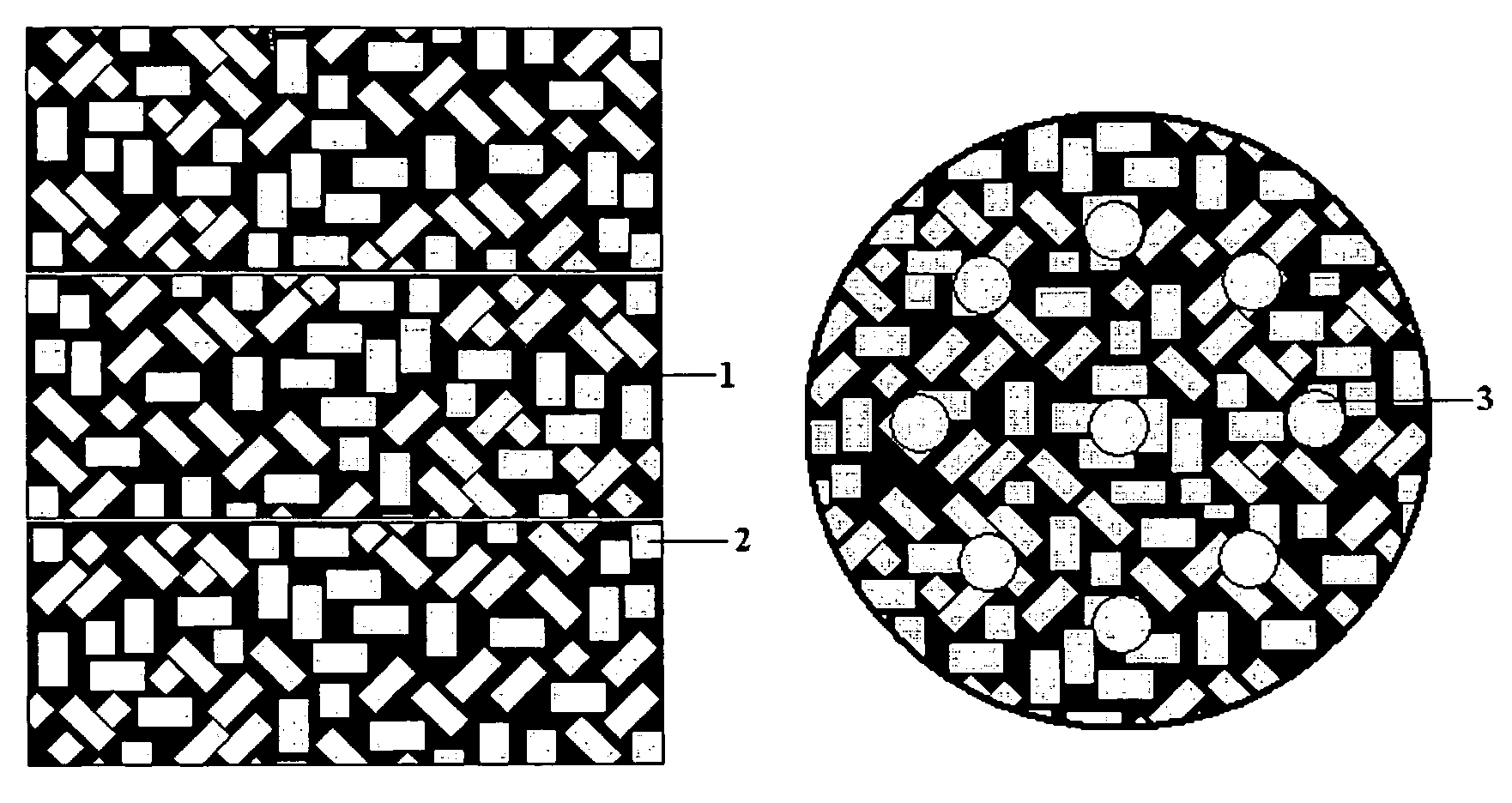
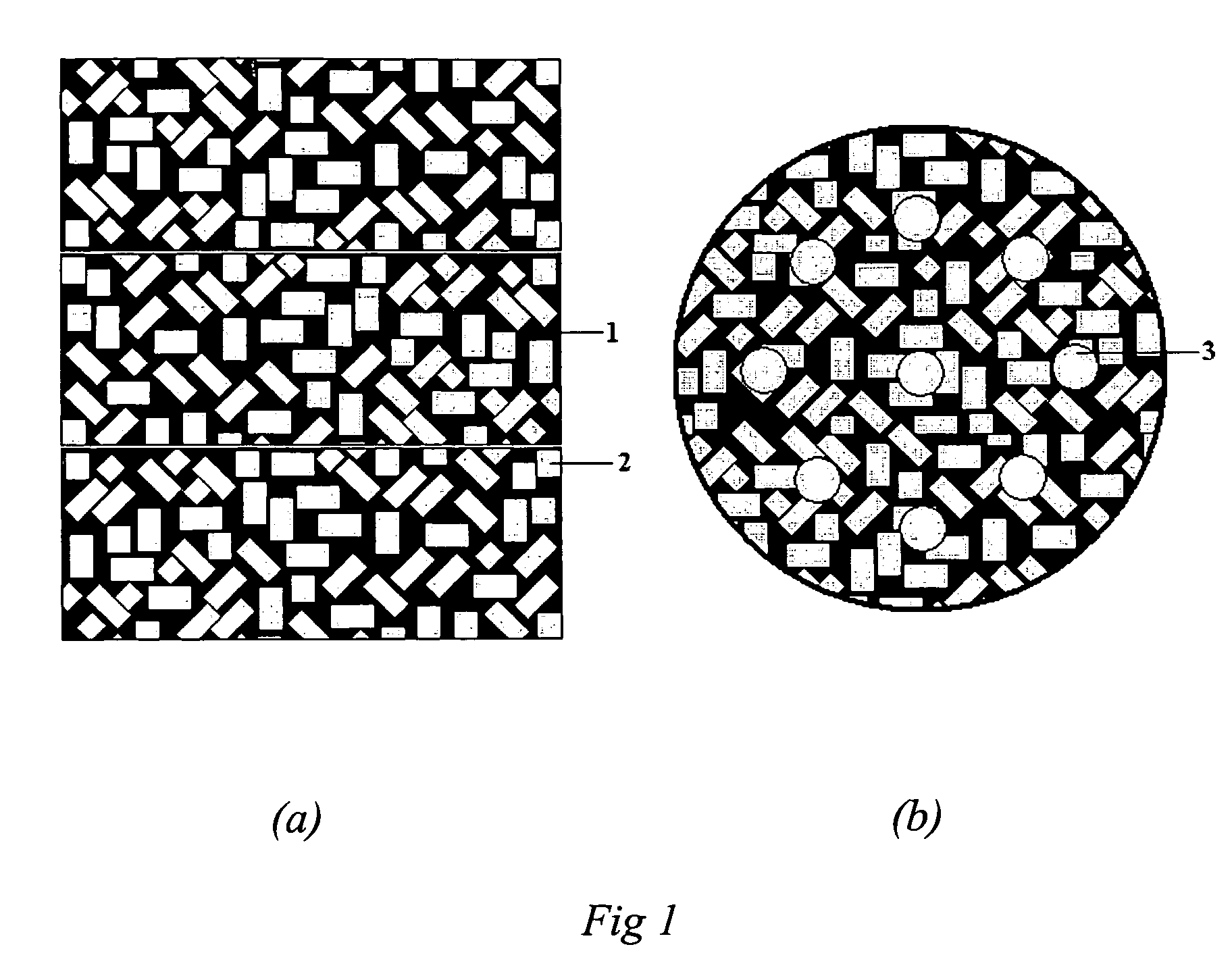
[0028]Zeolite 13X beads were mixed with zeolite 13X powder to yield approximately 60% by mass beads. The mixed zeolites were then mixed with an equal mass of a 20% colloidal silica in water solution. Carbon nanofibers, PYROGRAF®-II, was dispersed in water with the aid of the dispersant DISPERSAYD® and ball milled for 24 hours. Approximately 10% by weight of carbon nanofibers to mass of solids was added to the suspension of zeolite and colloidal silica. This mixture was blended until it appeared to be a relatively homogeneous mixture of zeolite and carbon and then poured into a mold made from 100-mesh stainless steel screen. The molded mixture was allowed to dry overnight at 50° C. and was subsequently cured for 4 hours at 300° C. The part was a solid monolith disk after removal from the stainless steel screen mold. A stack of such monolith disks are shown in FIG. 1(a) with zeolite beads 2 dispersed within a phase of carbon nano-fibers and zeolite powder 1. The molded monolith can be...

example 2

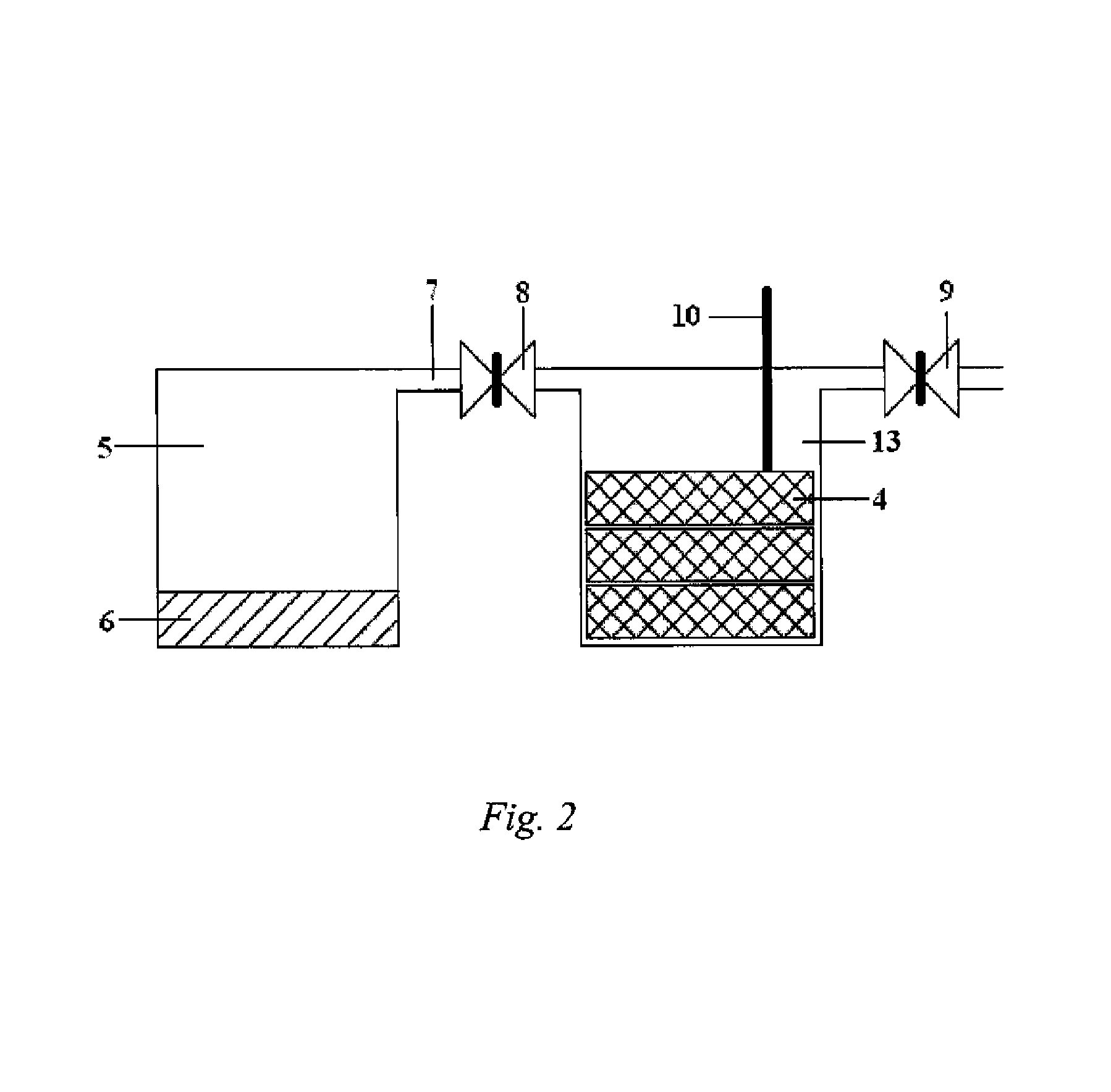
[0029]Zeolite monolith disks 4 were placed in a subscale test system's zeolite chamber 13 schematically shown in FIG. 2. Water 6 was added to second chamber 5 that was partially evacuated and placed in a condition of isolation with the zeolite chamber 13 by closing a master valve 8 that resides in a channel between the two chambers to permit vapor transport between the two chambers. With the master valve 8 closed, the zeolite chamber 13 was heated to 300° C. under vacuum through evacuation valve 9 to dry the zeolite of all water and remove all non-condensable permanent gasses.

[0030]The test system was then sealed under vacuum by closing valve 9. The master valve 8 was then opened between the two chambers 13 and 5. The temperature of the zeolite monolith was monitored via a thermocouple 10 inserted into the zeolite chamber 13. The maximum temperature in the zeolite chamber 13 upon absorption of water was only 70° C. The temperature change was 50° C. less than that for chamber 13 pack...


PUM

PropertyMeasurementUnit
temperature thermal conductivityaaaaaaaaaa
weight percentaaaaaaaaaa

Abstract

A monolith comprises a zeolite, a thermally conductive carbon, and a binder. The zeolite is included in the form of beads, pellets, powders and mixtures thereof. The thermally conductive carbon can be carbon nano-fibers, diamond or graphite which provide thermal conductivities in excess of about 100 W / m·K to more than 1,000 W / m·K. A method of preparing a zeolite monolith includes the steps of mixing a zeolite dispersion in an aqueous colloidal silica binder with a dispersion of carbon nano-fibers in water followed by dehydration and curing of the binder is given.

Description

STATEMENT REGARDING FEDERALLY SPONSORED RESEARCH OR DEVELOPMENT[0001]The United States Government has rights in this invention pursuant to contract no. DEAC05-00OR22725 between the United States Department of Energy.CROSS-REFERENCE TO RELATED APPLICATIONS[0002]Not applicable.FIELD OF THE INVENTION[0003]The present invention relates to high thermal conductivity adsorbent monolithic structures comprising zeolite, thermally conductive carbon, and a binder.BACKGROUND OF THE INVENTION[0004]The natural mineral zeolite (e.g. porous aluminosilicate) has the property of strongly adsorbing water vapor, incorporating it in its internal crystal lattice, with a significant release of heat. Water can be deabsorbed from zeolites by heating. The absorption process can proceed in a partially evacuated environment where the absorption of the water by the zeolite can be so forceful that the internal pressure of the closed system drops dramatically and causes liquid water in the system to evaporate and...

Claims


Application Information

Patent Timeline
Patent Type & Authority Patents(United States)
IPC IPC(8): B01J29/04F25B15/00
CPCB01J20/183B01J20/28042B82Y30/00B82Y40/00C01B31/0206C01B31/04C01B31/06C01B33/14C01B33/28C04B35/6316C04B35/803C04B38/0003C09K5/047F25B17/08C04B14/022C04B14/047C04B28/24C04B14/386B01J29/06B01J29/082B01J35/04B01J37/0009B01J2229/42C04B2235/3418C04B2235/3463C04B2235/5248C04B2235/9607F01P9/02C04B35/19C04B35/6269C04B35/80C04B2235/3201C04B2235/3472C04B2235/5472C01B32/15C01B32/20C01B32/25
Inventor KLETT, JAMESKLETT, LYNNKAUFMAN, JONATHAN
Owner UT BATTELLE LLC
Why Eureka
Eureka Blog
Learn More