Interrogator of communication system

a communication system and interrogator technology, applied in the field of interrogators, can solve the problems of not being able to satisfactorily detect signals, and achieve the effects of reducing the output of the combiner, reducing the possibility of frequency fluctuation, and high accuracy

Active Publication Date: 2010-08-31
BROTHER KOGYO KK
View PDF25 Cites 2 Cited by
  • Summary
  • Abstract
  • Description
  • Claims
  • Application Information

AI Technical Summary

Benefits of technology

[0009]In the interrogator constructed according to the invention, for example, by controlling the second local signal such that the second local signal coincides in phase with a desired wave and / or such that the second local signal is orthogonal to an interference wave, so as to make it possible to reduce main carrier component and interference wave component, thereby enabling a signal related to the modulation (performed by the transponder) and having a high signal-to-noise ratio, to be extracted. That is, the present invention provides the interrogator of the communication system that is capable of satisfactorily detecting a signal related to modulation performed by the transponder of the communication system.
[0030]According to the twentieth-first aspect of the invention, in the interrogator defined in the twentieth aspect of the invention, the frequency divider generates the frequency-divided signal, by frequency-dividing the intermediate frequency signal with a frequency division ratio of 0.2. This arrangement makes it possible to advantageously generate the clock signal of the analog-to-digital converter, based on the main carrier wave.

Problems solved by technology

However, since the signal related to the modulation performed by the transponder, i.e., transmitted information signal is provided by an extremely small signal, the conventional technique does not necessarily make it possible to satisfactorily detect the signal related to the modulation performed by the transponder, for example, where a communication distance is relatively long or where there exist reflected waves respectively transmitted from a plurality of transponders.

Method used


Image

  • Interrogator of communication system
  • Interrogator of communication system
  • Interrogator of communication system

Examples


first embodiment

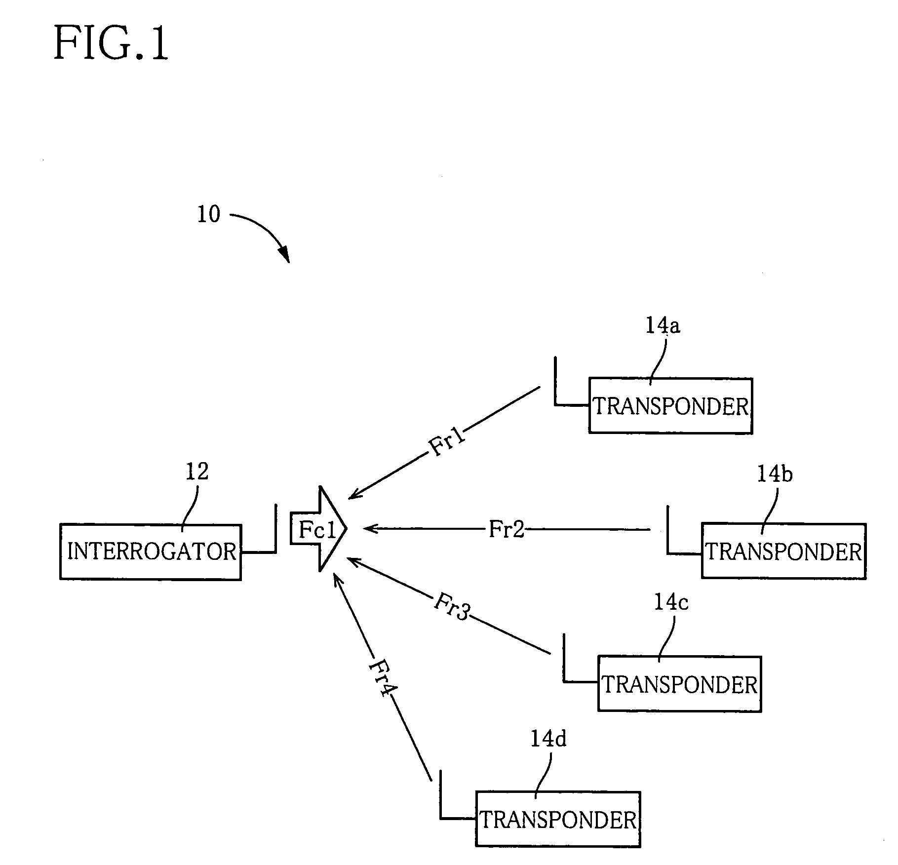
[0065]Referring first to FIG. 1, there is shown a communication system 10 to which the present invention is advantageously applied. This communication system 10 includes an interrogator 12 that is constructed according to a first embodiment of the invention, and a plurality of (e.g., a total of four) transponders 14a, 14b, 14c, 14d (which will be referred simply to as transponders 14 where they do not have to be particularly distinguished from each other). The interrogator 12 is operable to transmit an interrogating wave in the form of a main carrier wave Fc1 toward the transponders 14. The transponders 14a, 14b, 14c, 14d are operable, upon reception of the main carrier wave Fc1 transmitted from the interrogator 12, to respond to the interrogator 12 with response waves in the form of a reflected wave Fr1, a reflected wave Fr2, a reflected wave Fr3 and a reflected wave Fr4, respectively. That is, in the transponder 14a, the reflected wave Fr1 is generated by secondarily modulating th...

second embodiment

[0086]Referring next to FIGS. 19-22, there will be described an interrogator 60 that is constructed according to a second embodiment of the invention. In the following description of the second embodiment, the same reference signs as used in the above-described first embodiment will be used to identify the functionally corresponding elements.

[0087]As shown in FIG. 19, in the interrogator 60, the same number of intermediate signals IS as that of the communication channels are prepared as digital signals outputted from the A / D converter 24. The interrogator 60 includes a plurality of second frequency-converters in the form of the same number of second mixers 28a, 28b, 28c, . . . as that of the communication channels. The plurality of second mixers 28a, 28b, 28c, . . . are operable to generate respective demodulated signals DF, by multiplying the respective intermediate signals IS with respective second local signals LO2 that are different from each other with respect to the frequency ...

third embodiment

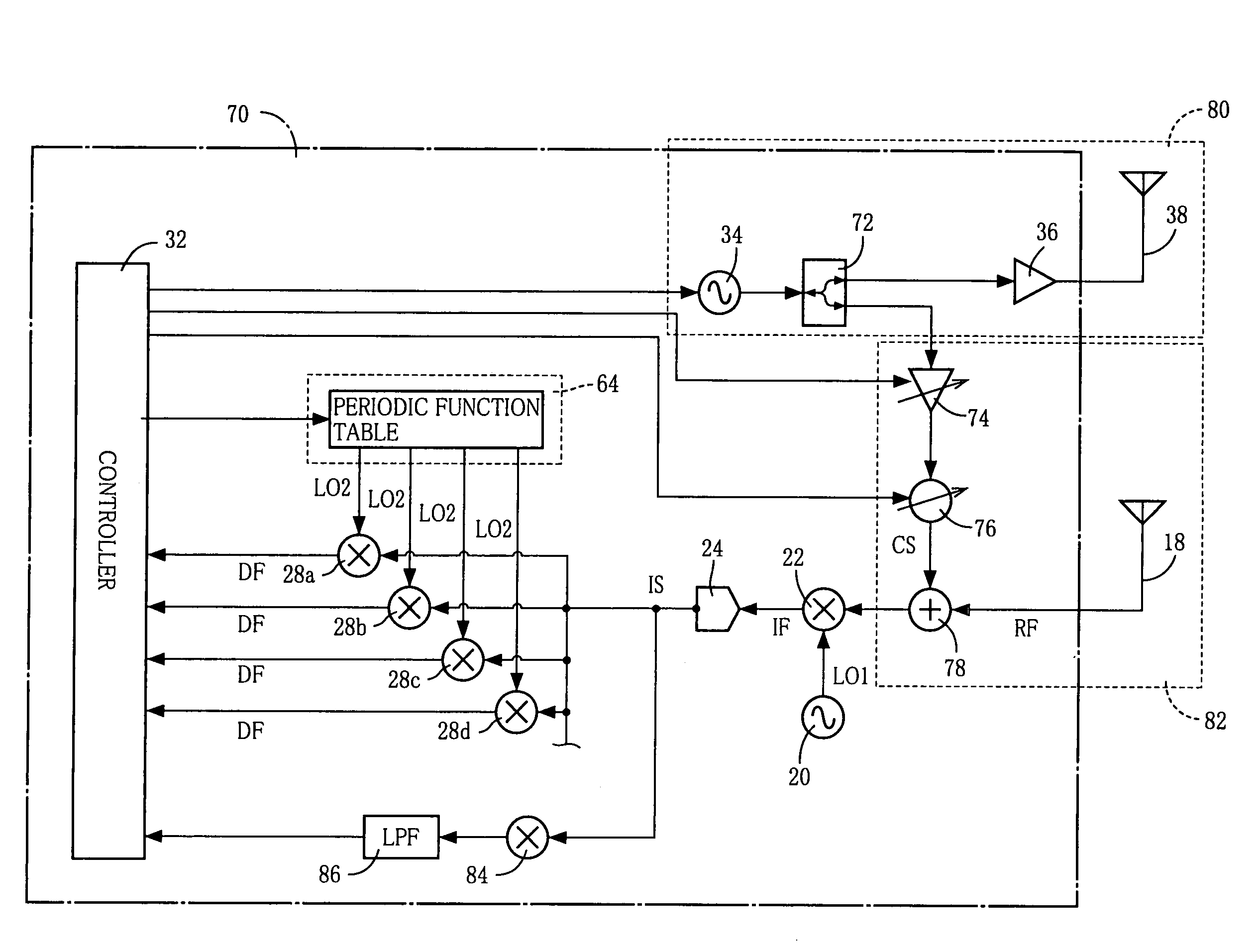
[0101]Referring next to FIGS. 23-26, there will be described an interrogator 70 that is constructed according to a third embodiment of the invention.

[0102]As shown in FIG. 23, the interrogator 70 includes: a distributor or divider 72 operable to divide the main carrier wave Fc1 generated by the main carrier oscillator 34, into a transmission signal and a cancel signal CS; a cancel-signal amplitude adjuster 74 operable to adjust amplitude of the cancel signal CS supplied from the divider 72; a cancel-signal phase adjuster 76 operable to adjust phase of the cancel signal CS; and a multiplexer 78 serving as a combiner operable to combine the cancel signal CS (whose amplitude and phase have been adjusted by the respective adjusters 74, 76) and the reflected wave Frf (received as the received signal RF by the receiving antenna 18). The multiplexer 78, after combining the cancel signal CS and the reflected wave Frf, outputs a composite signal, i.e., combination of the cancel signal CS and...


PUM


Abstract

An interrogator that is to be incorporated in a communication system in which each of at least one transponder is operable, upon reception of a main carrier wave transmitted from the interrogator, to respond to the interrogator with a reflected wave that is generated by modulating the main carrier wave. The interrogator includes: (a) a transmitting portion operable to transmit the main carrier wave; (b) a receiving portion operable to receive the reflected wave as a received signal; (c) at least one first frequency-converter each operable to generate an intermediate frequency signal, by multiplying the received signal with a first local signal that is generated by a first local oscillator; (d) at least one second frequency-converter each operable to generate a demodulated signal, by multiplying the intermediate frequency signal or a converted signal converted from the intermediate frequency signal, with a second local signal that is generated by a second local oscillator; and (d) a phase controller operable to control phase of the second local signal.

Description

[0001]This is a Continuation-In-Part of Application No. PCT / JP 2004 / 011354 filed on Aug. 6, 2004, which claims benefit of Japanese Patent Application No. 2003-296853 filed on Aug. 20, 2003. The entire disclosure of the prior applications is hereby incorporated by reference herein in its entirety.BACKGROUND OF THE INVENTION[0002]1. Field of the Invention[0003]The present invention relates to an interrogator that is to be incorporated in a communication system in which each of at least one transponder is operable, upon reception of a main carrier wave transmitted from the interrogator, to respond to the interrogator with a reflected wave that is generated by modulating the main carrier wave.[0004]2. Discussion of Related Art[0005]There is known a communication system in which each of at least one transponder is operable, upon reception of a main carrier wave transmitted from the interrogator, to respond to the interrogator with a reflected wave that is generated by modulating the main...

Claims


Application Information

Patent Timeline
Patent Type & Authority Patents(United States)
IPC IPC(8): G01S13/74G01S13/00H03J1/00G06K17/00H04B1/59H04B5/02
CPCH03J1/0008
Inventor NAGAI, TAKUYA
Owner BROTHER KOGYO KK
Why Eureka
Try Eureka