Control method of a direct injection system of the common rail type provided with a high-pressure fuel pump

a technology of fuel pump and common rail, which is applied in the direction of electrical control, process and machine control, instruments, etc., can solve the problems of not being able to adjust the instantaneous flow rate of the high-pressure pump with high accuracy, and the above-described solutions are mechanically complex, so as to achieve easy and cost-effective implementation

Inactive Publication Date: 2010-09-07
FAB ITAL MAGNETI MARELLI SPA
View PDF30 Cites 16 Cited by
  • Summary
  • Abstract
  • Description
  • Claims
  • Application Information

AI Technical Summary

Benefits of technology

[0010]It is the object of the present invention to provide a control method of a direct injection system of the common rail type provided with a high-pressure fuel pump, such a control method being free from the above-described drawbacks and, specifically, being easy and cost-effective to implement.

Problems solved by technology

However, both the above-described solutions for varying the instantaneous flow rate of the high-pressure pump are mechanically complex and do not allow to adjust the instantaneous flow rate of the high-pressure pump with high accuracy.
Furthermore, the flow rate adjustment device comprising a variable section bottleneck presents a small passage section in case of small flow rates and such small passage section determines a high local pressure loss (local load loss) which may compromise the correct operation of an intake valve which adjusts the fuel intake into a pumping chamber of the high-pressure pump.
It has been observed that there is a rather narrow critical angle at each pumping of the high-pressure pump; if the opening command of the shut-off valve is given at the critical angle, irregularities in the fuel delivery to the high-pressure pump may occur and such delivery irregularities subsequently cause a perturbation of the fuel pressure in the common rail.
In order to avoid sending the opening command of the shut-off valve at the critical pumping angle of the high-pressure pump, it has been suggested to phase the shut-off valve commands according to the pumping of the high-pressure pump; however such a solution requires to accurately know the pumping phase of the high-pressure pump (i.e. the mechanical actuation phase of the high-pressure pump) and thus forces to install an angular encoder in the high-pressure pump with a considerable increase of the costs (an angular encoder is a very expensive sensor and is rather cumbersome).
Alternatively to the installation of an angular encoder in the high-pressure pump, it is possible to use the signal provided with the phonic wheel which instantaneously detects the angular position of the drive shaft from which the motion which operates the high pressure pump is taken; however, in this case, it is necessary to perform a precision construction and assembly of the mechanical transmission which derives the motion from the drive shaft to operate the high-pressure pump and of the high-pressure pump itself with a considerable increase in the construction and assembly costs of such components.
In other words, the mechanical transmission which operates the high-pressure pump receives the motion from the drive shaft and thus presents an actuation frequency proportional to the revolution speed of the drive shaft (consequently, by knowing the revolution speed of the drive shaft the actuation frequency of the mechanical transmission which operates the high pressure pump is immediately known); however, due to construction and assembly limitations, the mechanical transmission which operates the high-pressure pump cannot guarantee the respect of the predetermined phase with respect to the drive shaft and thus the phase between the mechanical transmission which actuates the high-pressure pump and the drive shaft cannot be known in advance.

Method used


Image

  • Control method of a direct injection system of the common rail type provided with a high-pressure fuel pump
  • Control method of a direct injection system of the common rail type provided with a high-pressure fuel pump
  • Control method of a direct injection system of the common rail type provided with a high-pressure fuel pump

Examples


Embodiment Construction

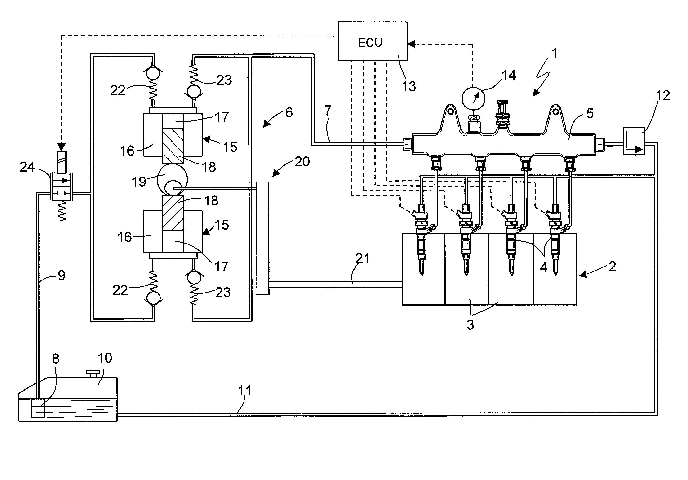
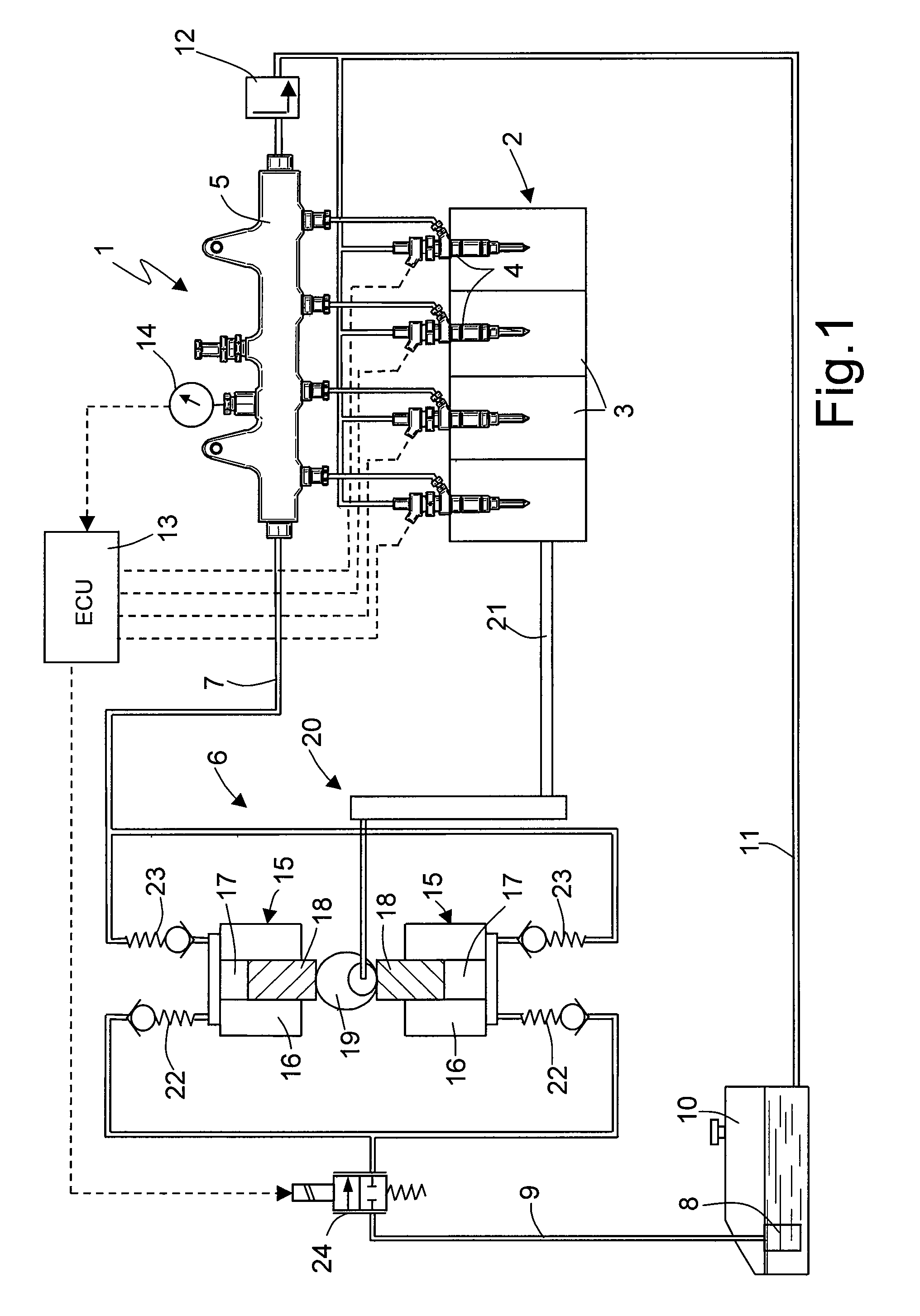
[0013]In the accompanying FIGURE, numeral 1 indicates a common rail type system as a whole for the direct fuel injection into an internal combustion engine 2 provided with four cylinders 3. The injection system 1 comprises four injectors 4, each of which presents a hydraulic needle actuation system and is adapted to inject fuel directly into a corresponding cylinder 3 of the engine 2 and to receive the pressurized fuel from a common rail 5.

[0014]A variable delivery high-pressure pump 6 feeds the fuel to the common rail 5 by means of a delivery pipe 7. In turn, the high-pressure pump 6 is fed by a low-pressure pump 8 by means of an intake pipe 9 of the high-pressure pump 6. The low-pressure pump 8 is arranged inside a fuel tank 10, onto which a discharge channel 11 of the fuel in excess of the injection system 1 leads, such a discharge channel 11 receiving the fuel in excess both from the injectors 4 and from a mechanical pressure-relief valve 12 which is hydraulically coupled to the...


PUM


Abstract

A control method of a direct injection system of the common rail in an internal combustion engine; the control method contemplates the steps of: feeding the pressurized fuel to a common rail by means of a high-pressure pump presenting at least one pumping element mechanically operated by a drive shaft of the internal combustion engine; measuring the angular position of the drive shaft; measuring the fuel pressure in the common rail; analyzing the oscillations of the fuel pressure in the common rail; and determining the phase of the pumping element of the high-pressure pump with respect to the drive shaft according to the oscillations of the fuel pressure in the common rail.

Description

TECHNICAL FIELD[0001]The present invention relates to a control method of an direct injection system of the common rail type provided with a high-pressure fuel pump.BACKGROUND ART[0002]In a direct injection system of the common rail type, a high-pressure pump receives a flow of fuel from a tank by means of a low-pressure pump and feeds the fuel to a common rail hydraulically connected to a plurality of injectors. The pressure of the fuel in the common rail must be constantly controlled according to the engine point either by varying the instantaneous flow rate of the high-pressure pump or by constantly feeding an excess of fuel to the common rail and by discharging the fuel in excess from the common rail itself by means of an adjustment valve. Generally, the solution of varying the instantaneous flow rate of the high-pressure pump is preferred, because it presents a much higher energy efficiency and does not cause an overheating of the fuel.[0003]In order to vary the instantaneous f...

Claims


Application Information

Patent Timeline
Patent Type & Authority Patents(United States)
IPC IPC(8): F02M57/02G01M19/00G01M99/00
CPCF02D41/3854F02M59/102F02M59/205F02M59/366F02M63/0225F02D41/009F02D41/123F02D2200/0602F02D2200/0604F02D2250/04
Inventor SERRA, GABRIELEDE CESARE, MATTEOPRODI, GIOVANNI
Owner FAB ITAL MAGNETI MARELLI SPA
Why Eureka
Try Eureka