Differential device

a technology of a differential device and a pinion shaft, which is applied in the direction of electric propulsion mounting, transportation and packaging, gearing, etc., can solve the problems of difficult to guide the lubricating oil, the sliding surface of the pinion shaft is liable to wear, and the configuration of the pinion shaft is extremely complicated, so as to achieve easy introduction and easy introduction. , the effect of easy introduction

Inactive Publication Date: 2010-09-07
TOYOTA JIDOSHA KK
View PDF18 Cites 4 Cited by
  • Summary
  • Abstract
  • Description
  • Claims
  • Application Information

AI Technical Summary

Benefits of technology

[0007]The present invention has been devised in light of the above-described problem, and an object of the present invention is to provide a differential device capable of providing lubricating oil to sliding surfaces between the pinion shaft and each pinion gear thereof in a sure and reliable manner, with a simple configuration.
[0010]In accordance with this feature of the present invention, upon rotation of the differential case, having a lower section thereof immersed in lubricating oil held within the bottom section of the casing, the lubricating oil is scooped up by the one end of each of the lubricating oil channels opening to the exterior of the differential case at the shaft-end corner sections of the pinion shaft corresponding to the rotation-direction upstream side of the differential case and introduced into the lubricating oil channels, and is provided to the sliding surfaces of the pinion shaft with respect to the pinion gears via the other ends of the lubricating oil channels opening to the sliding surfaces with respect to the pinion gears. As a result of this, even though the sliding surfaces of the pinion shaft with respect to each of the pinion gears are disposed inside the rotating differential case, lubricating oil is smoothly provided to the sliding surfaces of the pinion shaft with respect to the pinion gears via the lubricating oil channels. Consequently, even when a large rotation difference occurs between the left and right drive wheels, the sliding surfaces of the pinion shaft with respect to the pinion gears are sufficiently lubricated by the lubricating oil provided to the sliding surfaces of the pinion shaft, and as a result, wearing of the sliding surfaces of the pinion shaft can be effectively prevented.
[0013]In accordance with this feature of the present invention, lubricating oil sprayed by the lubricating oil spraying means provided at the bottom of the casing is, upon rotation of the differential case, sprayed towards the end of each of the lubricating oil channels opening to the exterior of the differential case at the shaft-end corner sections of the pinion shaft corresponding to the rotation-direction upstream side of the differential case, and the sprayed lubricating oil is introduced into the end of each of the lubricating oil channels and provided to the sliding surfaces of the pinion shaft with respect to the pinion gears from the other end thereof. As a result of this, even though the sliding surfaces of the pinion shaft with respect to each of the pinion gears are disposed inside the rotating differential case, lubricating oil is smoothly provided to the sliding surfaces of the pinion shaft with respect to each of the pinion gears via the lubricating oil channels. Therefore, even when a large rotation difference occurs between the left and right drive wheels, the sliding surfaces of the pinion shaft with respect to each of the pinion gears are sufficiently lubricated by the lubricating oil provided to the sliding surfaces of the pinion shaft, and as a result, wearing of the sliding surfaces of the pinion shaft can be effectively prevented.
[0015]Furthermore, even though the lower section of the differential case is not immersed in lubricating oil held within a bottom section of the casing, the lubricating oil sprayed by the lubricating oil spraying means can be sufficiently provided to the sliding surfaces of the pinion shaft with respect to the pinion gears by passing from the one end of the lubricating oil channels to the other end thereof, and therefore, this construction can be applied in any kind of differential device for provision of lubricating oil to the sliding surfaces of the pinion shaft, and the versatility of the provision construction for lubricating oil can be enhanced.
[0016]Furthermore, cut-away sections may be provided at portions of the differential case further upstream in the direction of rotation thereof than the pinion shaft and at the shaft-end corner sections of the pinion shaft corresponding to the rotation-direction upstream side positions of the differential case in order to expose the one end of each of the lubricating oil channels so as to face upstream in the direction of rotation of the differential case. As a result of this configuration, lubricating oil can be introduced easily and without impediment into the one end of the lubricating oil channels. Accordingly, when the one end of each of the lubricating oil channels moves down into the lubricating oil held within the bottom section of the casing upon rotation of the differential case, the lubricating oil can be guided smoothly and without impediment from the direction of rotation of the differential case and easily introduced via the end of the lubricating oil channel. Furthermore, lubricating oil sprayed from the lubricating oil spraying means can also be guided without impediment from a wide area and easily introduced via the one end of the lubricating oil channel. Accordingly, the introduction of the lubricating oil into each of the lubricating oil channels can be performed more smoothly due to the action of each of the cut-away sections, and this configuration is extremely beneficial in terms of the provision of the lubricating oil from the other end of each of the lubricating oil channels to the sliding surfaces of the pinion shaft with respect to the pinion gears.

Problems solved by technology

However, as the sliding surfaces of the pinion shaft with respect to each of the pinion gears are disposed inside the differential case, and in addition, the differential case itself is rotating, it is difficult to guide the lubricating oil having been stirred up by the final ring gear to the sliding surfaces of the pinion shaft with respect to each of the pinion gears, and the pinion gears slide thereupon in a substantially non-lubricated condition.
For this reason, if a large rotation difference occurs between the left and right drive wheels, the sliding surfaces of the pinion shaft are liable to wear.
However, in devices adopting the above approach, a strong sealing construction is required between a rotating body (that is, the driveshaft) and a fixed body (that is, the casing) upon guiding the lubricating oil from the casing to the hollow channel in the driveshaft, and the configuration thereof is extremely complicated.

Method used


Image

  • Differential device
  • Differential device
  • Differential device

Examples


first embodiment

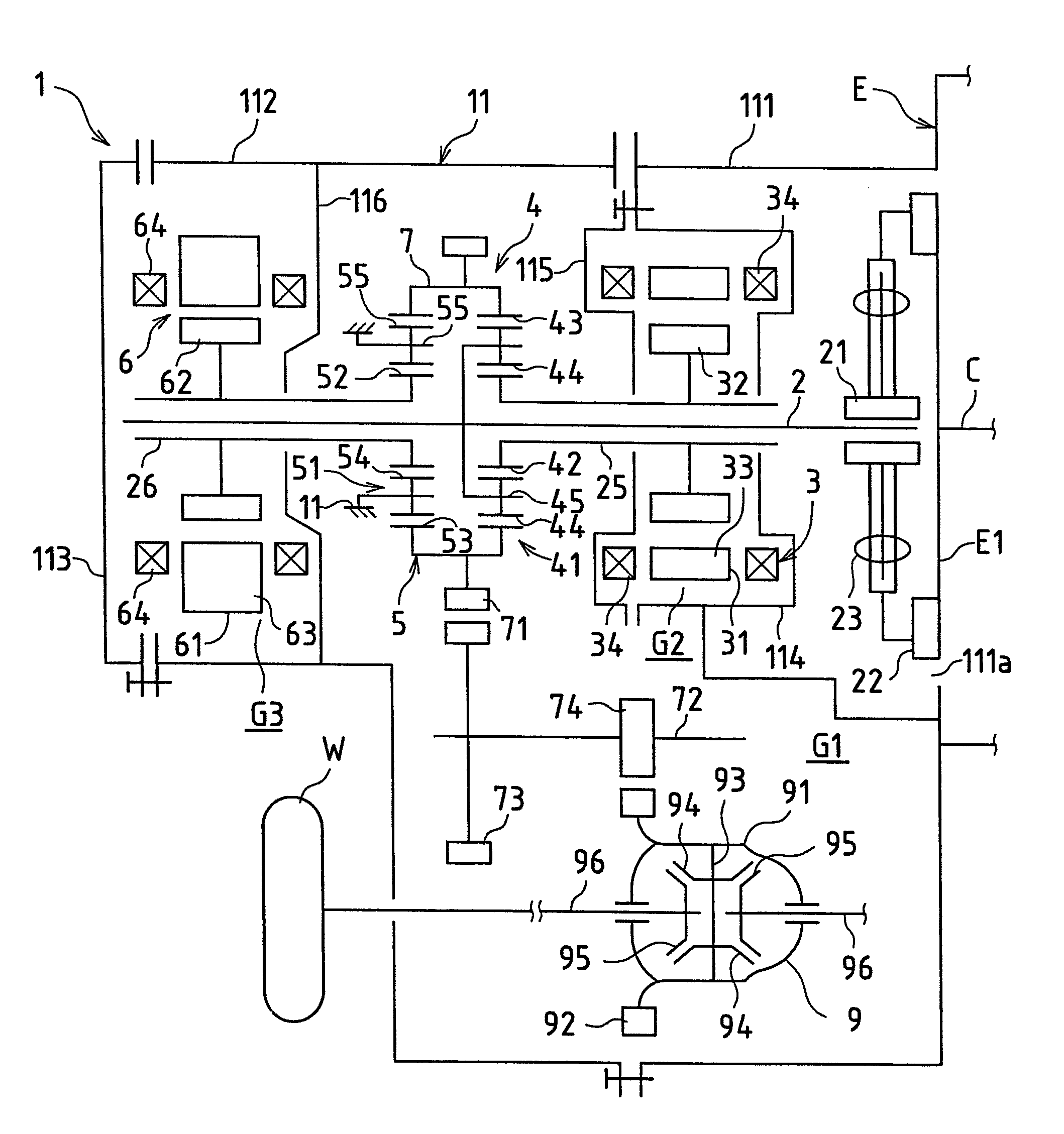
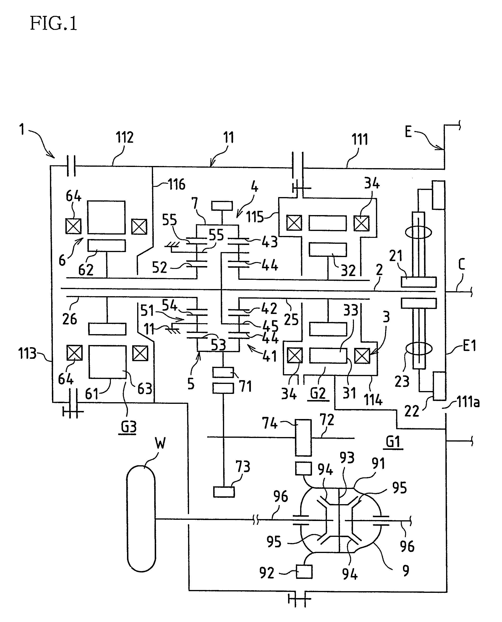
[0022]FIG. 1 shows a skeleton view of a transaxle of a hybrid vehicle of an FF configuration (that is, front-engine, front-drive; front-wheel drive having the engine mounted at the front of the vehicle) provided with a differential device according to a first embodiment of the present invention.

[0023]As shown in FIG. 1, a transaxle 1 is configured as a gear train including three shafts (an input shaft 2, a countershaft 72, and a front driveshaft 96, as explained hereinafter). Furthermore, an engine E is disposed at a side of the transaxle 1 (a right side in FIG. 1), and the transaxle 1 is configured so as to receive a drive force from the engine E. An internal combustion engine, specifically, a gasoline engine, a diesel engine, an LPG engine, a methanol engine, or a hydrogen engine, etc. may be used as the engine E. In this embodiment, the present invention is explained in terms of usage of a gasoline engine as the engine E. The engine E is configured such that motive energy can be ...

second embodiment

[0054]The following is a description of a second embodiment of the present invention, with reference to FIG. 4.

[0055]The second embodiment relates to a differential device configured so as to provide lubricating oil to a sliding surface of a pinion shaft with respect to a pinion gear in a situation wherein a lower section of a differential case is not immersed in lubricating oil at a bottom section of a transaxle case. It should be noted that, with the exception of the fact that the lower section of the differential case is not immersed in lubricating oil at the bottom section of the transaxle case, the configuration of the second embodiment is identical to that of the above-explained first embodiment, and therefore, the same reference symbols are used and a detailed explanation thereof is omitted.

[0056]That is to say, as shown in FIG. 4, an oil jet J spraying lubricating oil O towards an end of each of the lubricating oil channels 10 upon rotation of the differential case 91 is pro...


PUM


Abstract

An embodiment of a differential device of the present invention comprises a pair of side gears and a pair of pinion gears housed inside a differential case, with the pinion gears supported by a pinion shaft fixed to the differential case at axial end sections thereof so as to be capable of sliding freely thereabout. Lubricating oil channels are provided that pass through each of the end sections of the pinion shaft in the axial direction thereof. One end of each lubricating oil channel opens to the exterior of the differential case at a shaft-end corner section of the pinion shaft corresponding to an upstream side thereof in a direction of rotation of the differential case, and another end opens to a sliding surface of the pinion shaft with respect to one of the pinion gears. The differential device also comprises a mechanism for providing lubricating oil to the lubricating oil channels upon rotation of the differential case.

Description

BACKGROUND OF THE INVENTION[0001]This application seeks priority based on Patent Application No. 2007-35882, which was filed in Japan on Feb. 16, 2007. Accordingly, all of the content thereof is included in this application.[0002]The present invention relates to a differential device provided with a pair of side gears and a pair of pinion gears housed inside a differential case, and specifically, to a countermeasure for providing lubricating oil smoothly to sliding sections with a pinion shaft supporting each pinion gear so as to be capable of sliding freely.[0003]In vehicles such as automobiles, a rotation difference occurs between left and right drive wheels upon cornering, and therefore, a differential device has conventionally been provided in order to compensate for this rotation difference. As presented in JP 2004-90181A, for example, such a differential device includes a differential case, and a pair of side gears and a pair of pinion gears are housed therein. Furthermore, a ...

Claims


Application Information

Patent Timeline
Patent Type & Authority Patents(United States)
IPC IPC(8): F16H57/04F16H48/08F16H48/38
CPCB60K6/26B60K6/365B60K6/547F16H57/0427F16H57/0456F16H57/0483B60K1/02F16H2037/0866
Inventor FUJITA, HIROFUMIWATANABE, KAZUYUKIITO, TAKUYA
Owner TOYOTA JIDOSHA KK
Why Eureka
Try Eureka