High efficiency fiber-optic scintillator radiation detector

a radiation detector and high-efficiency technology, applied in the field of high-efficiency fiber-optic scintillator radiation detectors, can solve the problems of limited light acceptance angle of fiber-optic scintillators, achieve the effects of reducing detection cost, increasing 1/e length and detection sensitivity, and increasing detection sensitivity

Inactive Publication Date: 2010-09-07
CHARLES STARK DRAPER LABORATORY
View PDF7 Cites 12 Cited by
  • Summary
  • Abstract
  • Description
  • Claims
  • Application Information

AI Technical Summary

Benefits of technology

[0004]It is a further object of this invention to provide such an improved high-efficiency fiber-optic scintillator which allows for more efficient collection and propagation of scintillation photons.
[0005]It is a further object of this invention to provide such an improved high-efficiency fiber-optic scintillator radiation detector which increases 1 / e length and detection sensitivity, discrimination, energy resolution, positional uniformity, size of the effective detection area and reduced detection cost.
[0006]It is a further object of this invention to provide such an improved high-efficiency fiber-optic scintillator radiation detector which increases the scintillation photon acceptance angle and thus improves radiation detection sensitivity, discrimination and energy resolution.
[0007]The invention results from the realization that an improved fiber-optic scintillator radiation detector which more efficiently collects and propagates light, can be achieved by decoupling the core and scintillator with the scintillator contiguous with the core in the cladding and responsive to radiation for providing scintillation photons primarily propagated in the core.

Problems solved by technology

However, the light acceptance angle in a fiber-optic scintillator is limited by the total-internal-reflection (TIR) requirement.

Method used


Image

  • High efficiency fiber-optic scintillator radiation detector
  • High efficiency fiber-optic scintillator radiation detector
  • High efficiency fiber-optic scintillator radiation detector

Examples


Embodiment Construction

[0025]Aside from the preferred embodiment or embodiments disclosed below, this invention is capable of other embodiments and of being practiced or being carried out in various ways. Thus, it is to be understood that the invention is not limited in its application to the details of construction and the arrangements of components set forth in the following description or illustrated in the drawings. If only one embodiment is described herein, the claims hereof are not to be limited to that embodiment. Moreover, the claims hereof are not to be read restrictively unless there is clear and convincing evidence manifesting a certain exclusion, restriction, or disclaimer.

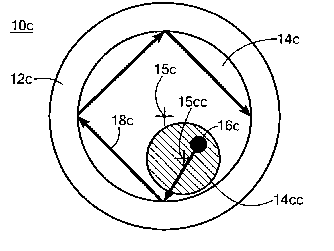
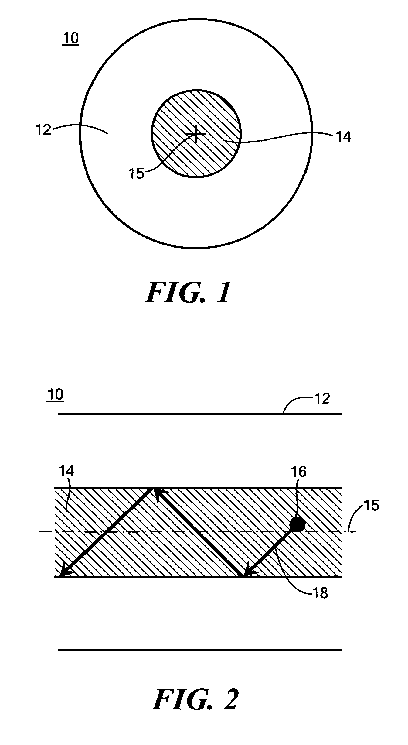
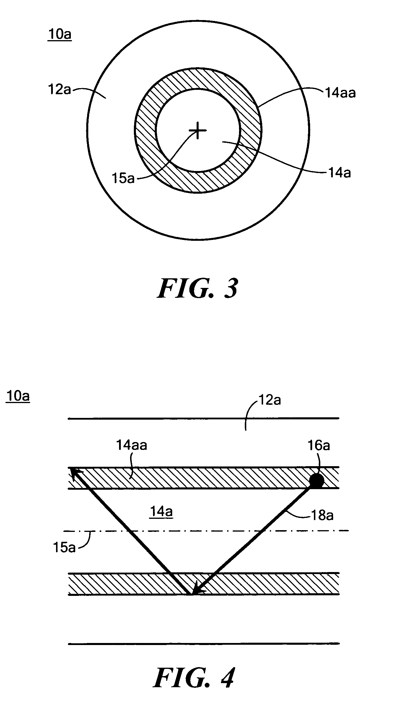
[0026]There is shown in FIG. 1 a prior art fiber-optic scintillator radiation detector 10 including a cladding 12 typically made of glass or polymer having an index of refraction ncl. Inside of the cladding 12 is a combination core and scintillator 14 which couples the function of the scintillator and the core in one medium...


PUM


Abstract

A fiber-optic scintillation radiation detector includes: a cladding; a core extending within the cladding; and a scintillator contiguous with the core within the cladding responsive to particle and / or photon radiation by providing scintillation photons, which are then primarily propagated in the core.

Description

FIELD OF THE INVENTION[0001]This invention relates to an improved high efficiency fiber-optic scintillator radiation detector.BACKGROUND OF THE INVENTION[0002]Scintillating materials are commonly used in low-threshold radiation detectors. Such materials generate detectable light pulses as a result of interaction with specific types of particle or photon radiation. Recently, novel scintillating materials have been developed that can be drawn into optical fiber form. The light-guide property of the fiber collects scintillation light generated over the entire length of the fiber and delivers it to the fiber end facets. Current standard fiber-optic scintillators are made with a scintillator core surrounded by a cladding. An advantage of the “fiber-optic scintillator” detector is that it allows for the creation of relatively inexpensive, robust and versatile, large-area radiation detectors. The scintillating materials used in current fiber-optic detectors typically exhibit significant at...

Claims


Application Information

Patent Timeline
Patent Type & Authority Patents(United States)
IPC IPC(8): G01J1/58
CPCG01T1/20
Inventor LAINE, JUHA-PEKKA J.MIRAGLIA, PETERTAPALIAN, JR., H. CHARLES
Owner CHARLES STARK DRAPER LABORATORY
Why Eureka
Try Eureka