Ground loop locator

a ground loop and locator technology, applied in the direction of short-circuit testing, testing circuits, instruments, etc., can solve the problems of affecting the accuracy of ground loop locators, so as to facilitate the method, reduce the size and cost, and facilitate the effect of location accuracy

Active Publication Date: 2010-09-07
CALIFORNIA INST OF TECH
View PDF2 Cites 5 Cited by
  • Summary
  • Abstract
  • Description
  • Claims
  • Application Information

AI Technical Summary

Benefits of technology

[0019]The invention disclosed herein is a system that provides for rapid and accurate location of single or multiple ground loops. The system is non-contacting, does not require disconnecting any cables, and the equipment can be powered on while the ground loop is being located. The system operates at much higher frequencies than other ground loop locators, which reduces the size and cost. The system also facilitates a methodology for rapidly identifying which of a group of similar- or identical-looking cables is causing a ground loop. The system is sufficiently simple and inexpensive that it could be configured as a permanent addition to any electronic instrument to provide a warning whenever a ground loop becomes established, or one can have a hand-held, highly portable system for identifying ground loops.
[0032]In yet another aspect, the Rogowski coil comprises a first coil portion and a second coil portion, the first coil portion hingedly connected with the second coil portion, whereby the Rogowski coil can easily be wrapped around cables or groups of cables.
[0038]In yet another aspect, the transformer is a split-core transformer, whereby the transformer can easily be wrapped around cables or groups of cables.

Problems solved by technology

There are many reasons for the existence of ground loops; they might be due to an accidental connection to ground (ground fault) or may be due to an inadvertent shortcoming of the system design.
Regardless of the cause of ground loops, currents can flow in these loops, resulting in spurious, unwanted, and often confusing signals; these signals due to ground loops interfere with low-level signals typical of laboratory environments and instruments.
In extreme situations, currents flowing in ground loops can even be dangerous, damaging equipment and endangering personnel.
Ground loops are not only a problem in research laboratories but also in the video and audio recording industries, temperature and humidity sensors used in building automation, medical diagnostics, and in the home where interconnected audio / video systems are notorious for producing ground loops.
Ground loops are especially hazardous in pulsed-power systems, such as plasma and fusion experiments, because the large and rapidly changing stray magnetic fields in these systems can induce enormous transient voltages.
In addition, ground loops in pulsed-power systems are notoriously hard to find because of the transient nature of the pulsed magnetic fields.
This diagnostic method can be tedious if there are large numbers of cables and becomes impractical if more than one ground loop exists because, in such a case, disconnecting any single cable will not reveal the ground loop.
Obviously, disconnecting large numbers of cables tends to disable equipment, making it difficult to simultaneously generate a ground loop and search for it.
However, each one of these references suffers from one or more of the following disadvantages: requiring physical, invasive contact to circuits, such as soldering or clipping; operating at a frequency which is too low to measure the inductive impedance and thus the size of ground loops; lack of portability or incapable of being “hand-held”; requiring computers or complicated algorithms to operate; consuming too much power to be battery-operated; using large amounts of high-permeability magnetic materials, requiring increase costs; being quite large, further increasing costs; lacking a “binary” response to ground loops; and overcoupling the detector to ground loops, which tends to change the circuit under test.

Method used


Image

  • Ground loop locator
  • Ground loop locator
  • Ground loop locator

Examples


Embodiment Construction

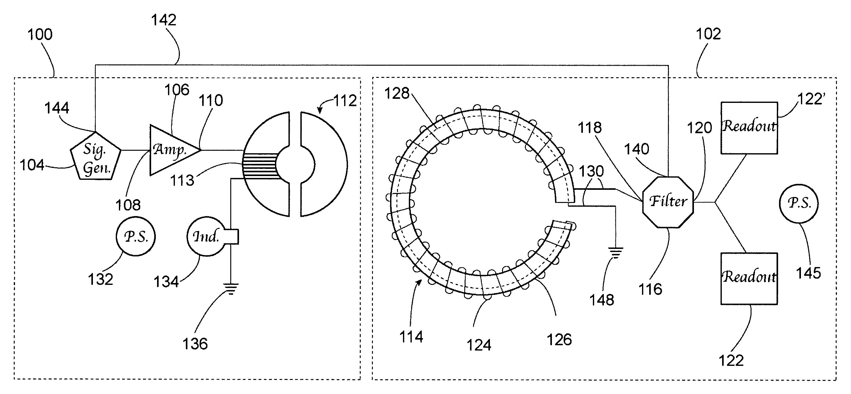
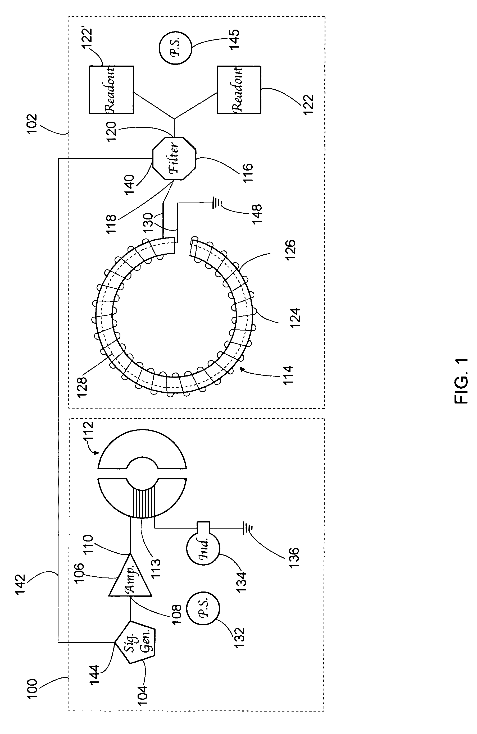
[0052]The present invention relates to devices and methods for detecting ground loops, more particularly to the field of devices and methods for detecting ground loops using hand-held, portable exciters and receivers, and still more particularly to devices and methods for detecting ground loops using hand-held, portable AC exciters and receivers that are sensitive to the inductance of ground loops. The following description is presented to enable one of ordinary skill in the art to make and use the invention and to incorporate it in the context of particular applications. Various modifications, as well as a variety of uses in different applications will be readily apparent to those skilled in the art, and the general principles defined herein may be applied to a wide range of embodiments. Thus, the present invention is not intended to be limited to the embodiments presented, but is to be accorded the widest scope consistent with the principles and novel features disclosed herein.

[00...


PUM


Abstract

Described is a ground loop locator. A readout on the ground loop locator indicates the presence of a ground loop when a ground loop exists in conductors linked by a current transformer of an exciter portion and a Rogowski coil of a detector portion. Also described are how to make and use the ground loop locator and methods of use for the ground loop locator.

Description

PRIORITY CLAIM[0001]The present invention claims the benefit of priority of U.S. Provisional Application No. 60 / 901571, filed on Feb. 13, 2007, entitled “Ground loop locator.”GOVERNMENT RIGHTS[0002]The U.S. Government has certain rights in this invention pursuant to Grant No. DE-FG02-04ER54755 / T-103336 awarded by DOE.BACKGROUND[0003](1) Field[0004]The field of the present invention relates to devices and methods for detecting ground loops, more particularly to the field of devices and methods for detecting ground loops using hand-held, portable exciters and receivers, and still more particularly to devices and methods for detecting ground loops using hand-held, portable AC exciters and receivers that are sensitive to the inductance of ground loops.[0005](2) Related Art[0006]Ground loops occur when electrical or electronic equipment are interconnected so as to develop unwanted paths to ground. There are many reasons for the existence of ground loops; they might be due to an accidenta...

Claims


Application Information

Patent Timeline
Patent Type & Authority Patents(United States)
IPC IPC(8): G01R31/08
CPCG01R31/024G01R31/52
Inventor BELLAN, PAUL M.
Owner CALIFORNIA INST OF TECH
Why Eureka
Try Eureka