Modular fore-end rail assembly with locking mechanism

a module and locking mechanism technology, applied in the direction of weapons, butts, weapon cleaning, etc., can solve the problems of limiting the access of the receiver, affecting the safety of the receiver, and many military personnel have multiple sighting devices, etc., and achieve the effect of convenient removal

Active Publication Date: 2010-09-14
SAMSON MFG
View PDF61 Cites 98 Cited by
  • Summary
  • Abstract
  • Description
  • Claims
  • Application Information

AI Technical Summary

Benefits of technology

[0008]In this regard, the present invention provides for modular fore-end rail assembly that is mounted onto a firearm that serves both as a handguard system and as an integrated interface system for mounting attachments thereto. The present invention is particularly directed to an improved modular fore-end rail assembly that includes a locking mechanism to enable quick detachment of the lower handguard or lower firearm accessory for access to the barrel without requiring the removal of the entire assembly from the firearm. The modular fore-end rail assembly further provides for a lower handguard that may be easily removed with a single hand. Further, by providing for the easy removal of the lower handguard, other auxiliary devices may be mounted to the upper handguard. For example, an M203 grenade launcher can be mounted to the upper handguard in place of the lower handguard portion.

Problems solved by technology

The difficulty is that many military personnel have multiple sighting devices in addition to a variety of lighting devices, accessory handgrips, etc. that could also be attached to the weapon 100 for enhanced use of the weapon 100.
However, prior art mounting systems often limit access to the receiver 102,104, barrel 108 and barrel nut 110 assembly.
This situation is undesirable because it limits servicing of the weapon 100 to qualified weapon smiths with appropriate tools and setting, e.g. an armory.

Method used


Image

  • Modular fore-end rail assembly with locking mechanism
  • Modular fore-end rail assembly with locking mechanism
  • Modular fore-end rail assembly with locking mechanism

Examples


Embodiment Construction

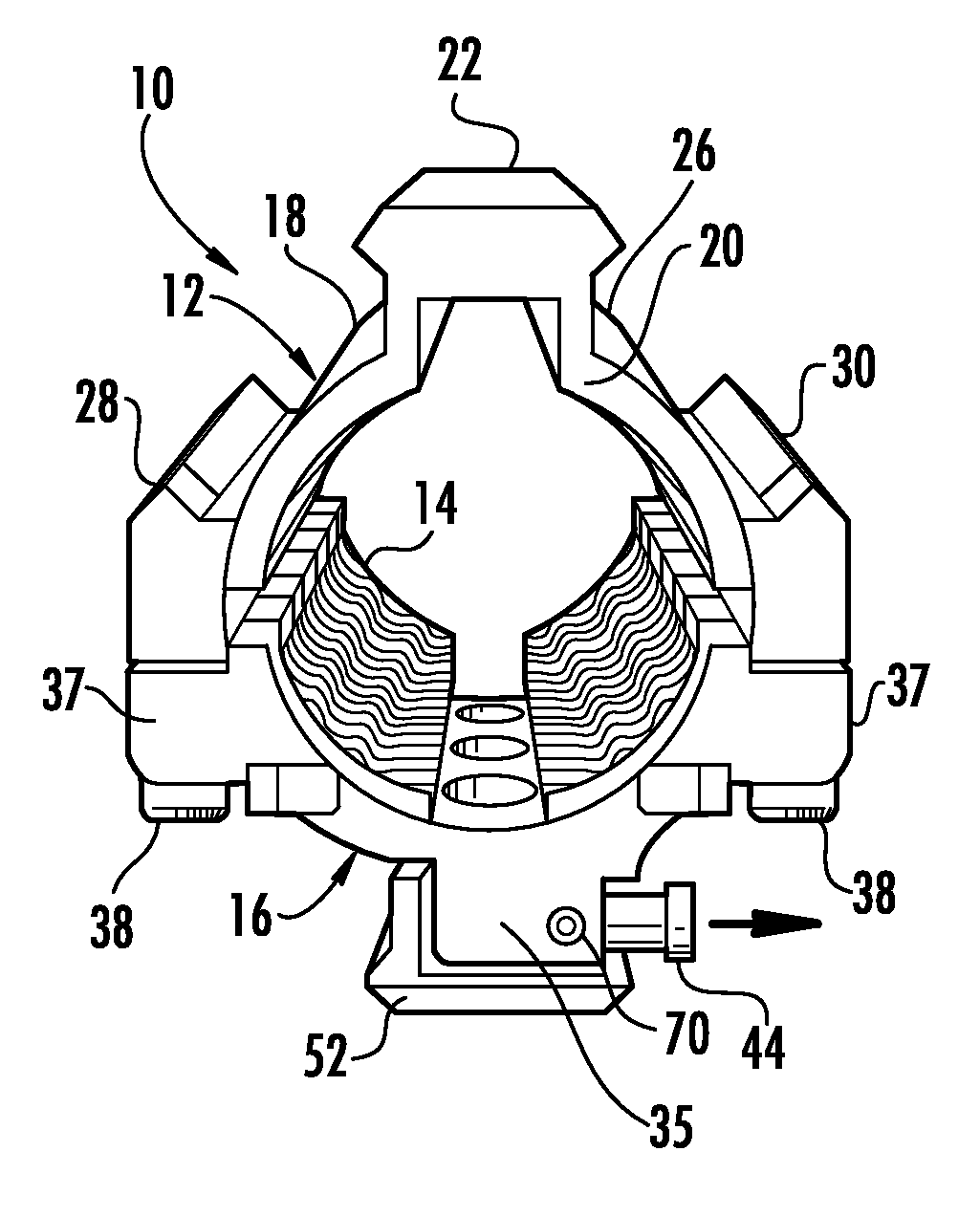
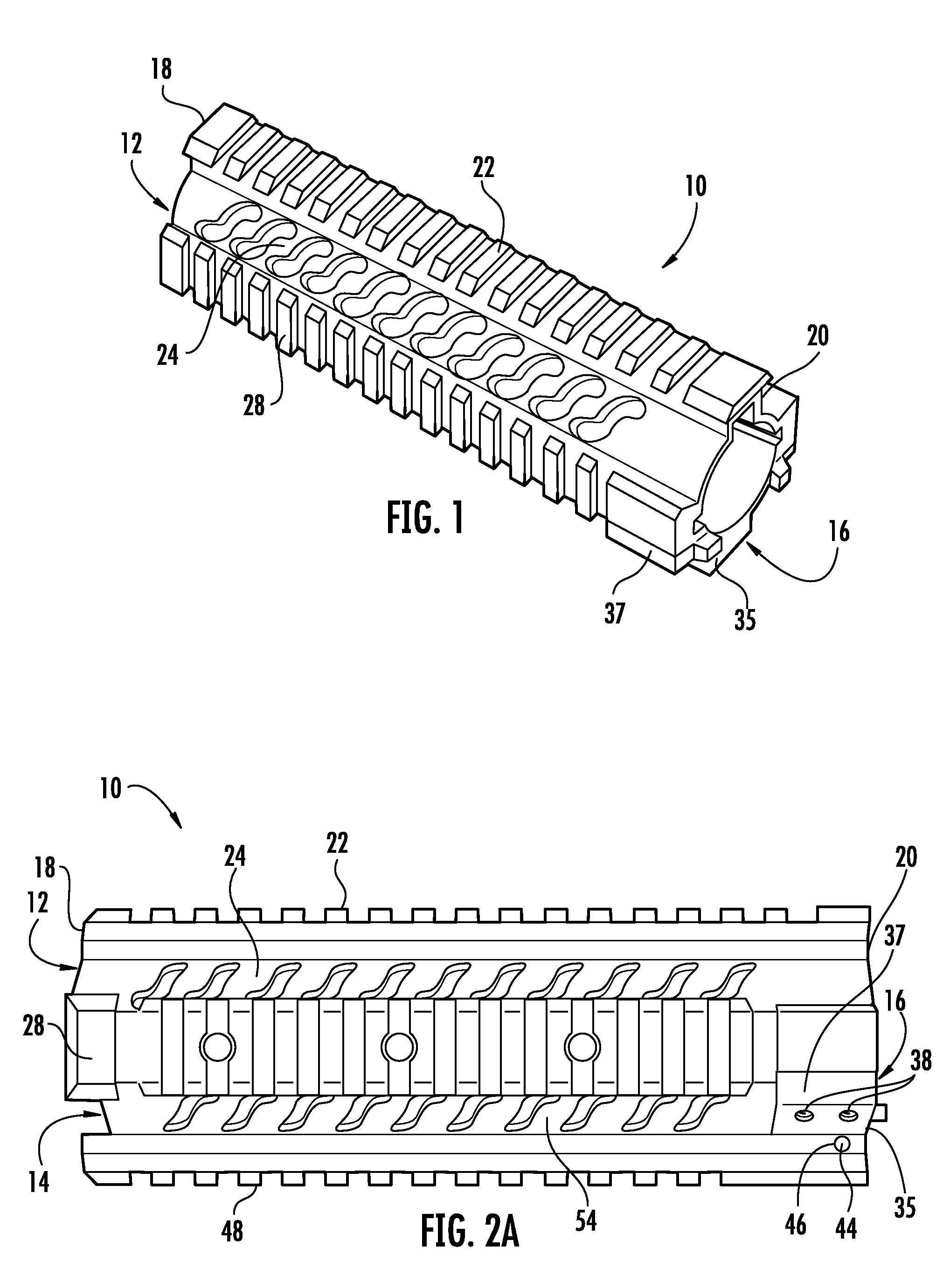
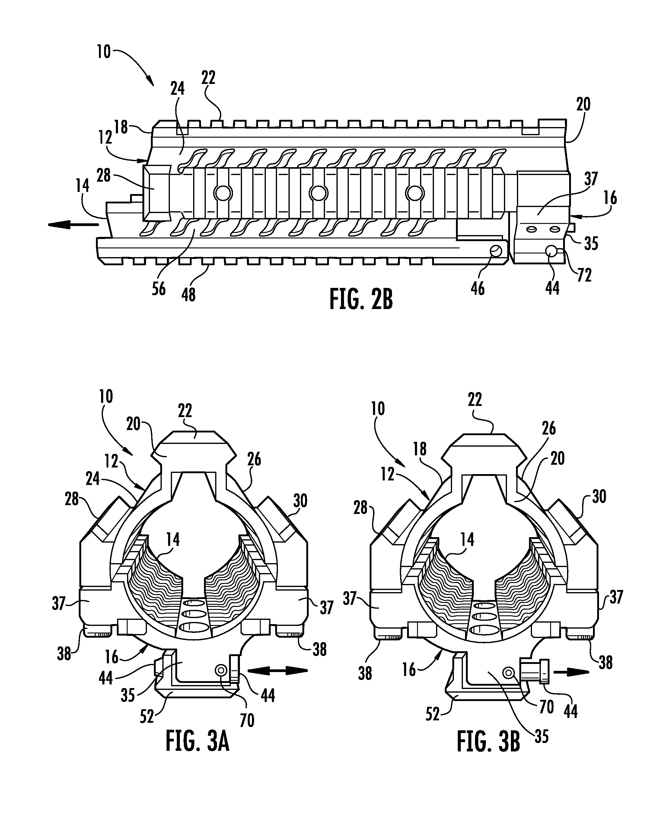
[0026]Referring now to FIGS. 1, 2A and 2B, the modular fore-end rail assembly 10 of the present invention generally includes an upper handguard portion 12, a lower handguard portion 14 and a clamping assembly 16.

[0027]The upper handguard portion 12 is the structural element that supports the entire modular assembly 10. The upper handguard portion 12 is formed generally as the upper half of a tubular enclosure that is configured to encircle the barrel of the firearm when in a mounted position. The upper handguard portion 12 has a forward end 18 and a rearward end 20 and a standard dovetail rail 22 extending longitudinally between the forward end 16 and the rearward end 18. The upper handguard portion 12 has left and right side walls 24, 26 that extend generally outwardly and downwardly from the dovetail rail 22 forming the upper half of the tubular enclosure. The left and right side walls 24, 26 each have an interior and exterior surface and the walls 24, 26 each terminate at their l...


PUM


Abstract

A modular fore-end rail assembly for a firearm is disclosed. The assembly includes an upper handguard having forward and rearward ends. A dovetail rail extends between the forward and rearward ends. Opposing sidewalls extend outwardly and downwardly from the dovetail rail, respectively. The sidewalls terminate in mounting channels. The rearward end includes a first clamping member. A clamp is removably secured to the rearward end and cooperates with the first clamping member to engage a barrel nut of a firearm. The clamp has an exterior surface including a slidable locking pin movable between a locked position and an unlocked position. A lower handguard includes sidewalls that extend outwardly and upwardly. The sidewalls terminate in mating formations that are configured to be slidably received in the mounting channels. A lock aperture is provided at a rearward end of the lower handguard. The locking pin may be slidably engaged with the lock aperture to selectively retain the lower handguard to the upper handguard.

Description

CROSS-REFERENCE TO RELATED APPLICATION[0001]The present patent document claims priority to earlier filed U.S. Provisional Patent Application Ser. No. 61 / 022,627, filed on Jan. 22, 2008, the entire contents of which are incorporated herein by reference.BACKGROUND OF THE INVENTION[0002]1. Field of the Invention[0003]The present invention relates generally to a modular fore-end rail assembly for firearms. More specifically, the present invention relates to a modular fore-end rail assembly for retrofitting a firearm that includes an upper handguard portion that is clamped around and supported by the barrel nut and further including a removable lower handguard portion that is mounted onto the upper handguard portion to fully surround the firearm barrel. The lower handguard further includes a locking mechanism to keep it assembled to the upper handguard.[0004]2. Background of the Related Art[0005]In the general field of combat and commercial weaponry, there is a broad range of accessories...

Claims


Application Information

Patent Timeline
Patent Type & Authority Patents(United States)
IPC IPC(8): F41C23/00
CPCF41C23/16
Inventor SAMSON, SCOTT W.LANKARGE, KENNETH
Owner SAMSON MFG
Why Eureka
Try Eureka