Thread stand for sewing machine

a technology for sewing machines and thread spools, applied in the direction of spool-pin assemblies, thin material processing, textiles and paper, etc., can solve the problems of insufficient mounting stability of thread spools, high cost, and excessive number of spool pins, etc., to facilitate attachment and enhance stability

Inactive Publication Date: 2010-09-14
TOKAI IND SEWING MACH CO LTD
View PDF13 Cites 6 Cited by
  • Summary
  • Abstract
  • Description
  • Claims
  • Application Information

AI Technical Summary

Benefits of technology

[0006]In view of the foregoing, it is an object of the present invention to provide an improved thread stand which allows a thread spool to be supported with an enhanced stability without requiring subsequent mounting of a special connection member and which can facilitate attachment, to a thread stand plate, of a spool pin.
[0007]It is another object of the present invention to provide an improved thread stand which can stably support any one of thread spools of at least two different types without requiring subsequent mounting or replacement of a special connection member.
[0009]Because the connection member integrally includes the supporting section, cylindrical portion and fitting portion, only attaching the connection member to the thread stand section (i.e., thread stand plate) of the sewing machine via the fitting portion allows the rod member (i.e., thread pin) to be readily attached to the thread stand section via the cylindrical portion of the connection member, and the thread spool can be supported stably with a reduced number of component parts. Further, by only inserting the one end portion of the rod member (thread pin) into or onto the cylindrical portion, the rod member (thread pin) can be attached to the thread stand section (i.e., thread stand plate) through one-touch operation. As a result, a thread spool can be supported with an enhanced stability, only through the novel attaching construction of the thread stand, without subsequent mounting of a special connection member, and, in addition, attachment, to the thread stand section (thread stand plate), of the rod member (i.e., thread pin) can be greatly facilitated.
[0012]In a preferred embodiment, the cylindrical portion and the fitting portion are formed, on the connection member, in coaxial positional relation to each other, and, when the one end portion of the rod member is inserted into or onto the cylindrical portion, the fitting portion resiliently deforms, due to a fitting force given by the rod member, into tight fitting engagement with the predetermined mounting portion of the thread stand section (thread stand plate) of the sewing machine, so that the connection member and the rod member can be tightly fixed to the thread stand section. Thus, through the one-touch operation of inserting the rod member into or onto the cylindrical portion, the connection member and the rod member (i.e., thread pin) can be reliably fixed to the thread stand section (i.e., thread stand plate), so that attachment, to the thread stand section (thread stand plate), of the rod member (i.e., thread pin) can be facilitated even further.

Problems solved by technology

However, with sewing machines having a great many thread spools to be supported substantially upright, such as industrial multiH-head embroidery sewing machines, screwing the extremely the extremely many spool pins 52 would require great amounts of time and labor and hence high cost.
However, with the construction disclosed in Patent Literature 1, where the spool pin is fitted directly into the thread stand plate and the thread spool is supported only by the spool pin and thread stand plate, mounting stability of the thread spool tends to be insufficient if the inner open space of the winding core is greater than the thickness of the spool pin.
However, because it is necessary to use a dedicated connection member for each individual special type of thread spool and thus change the type of connection member to be used per change in the type of thread spool to be set on the sewing machine, which would involve very cumbersome operation.

Method used


Image

  • Thread stand for sewing machine
  • Thread stand for sewing machine
  • Thread stand for sewing machine

Examples


Embodiment Construction

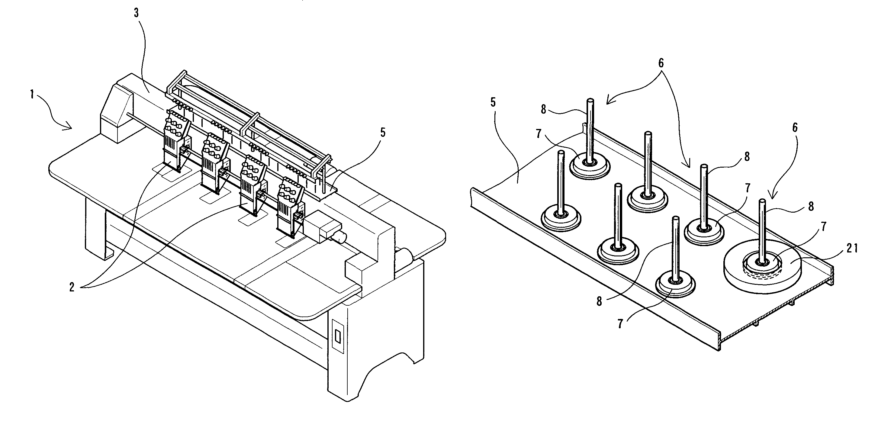
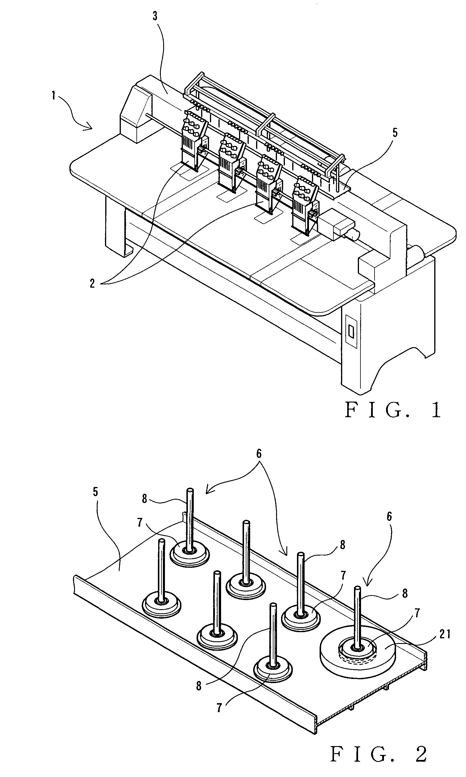
[0025]FIG. 1 is an outer appearance view of a multi-head, multi-color embroidery sewing machine 1, equipped with four machine heads, to which is applied a thread stand according to an embodiment of the present invention. Thread stand plate (thread stand section) 5 is provided on the upper surface of a machine frame 3 supporting thereon the four machine heads 2. The thread stand plate 5 is an elongated plate formed by drawing of aluminum and extending across all of the machine heads 2. As shown in enlarged scale in FIG. 2, a plurality of the thread stands 6 of the present invention are provided on the thread stand plate 5, per machine head.

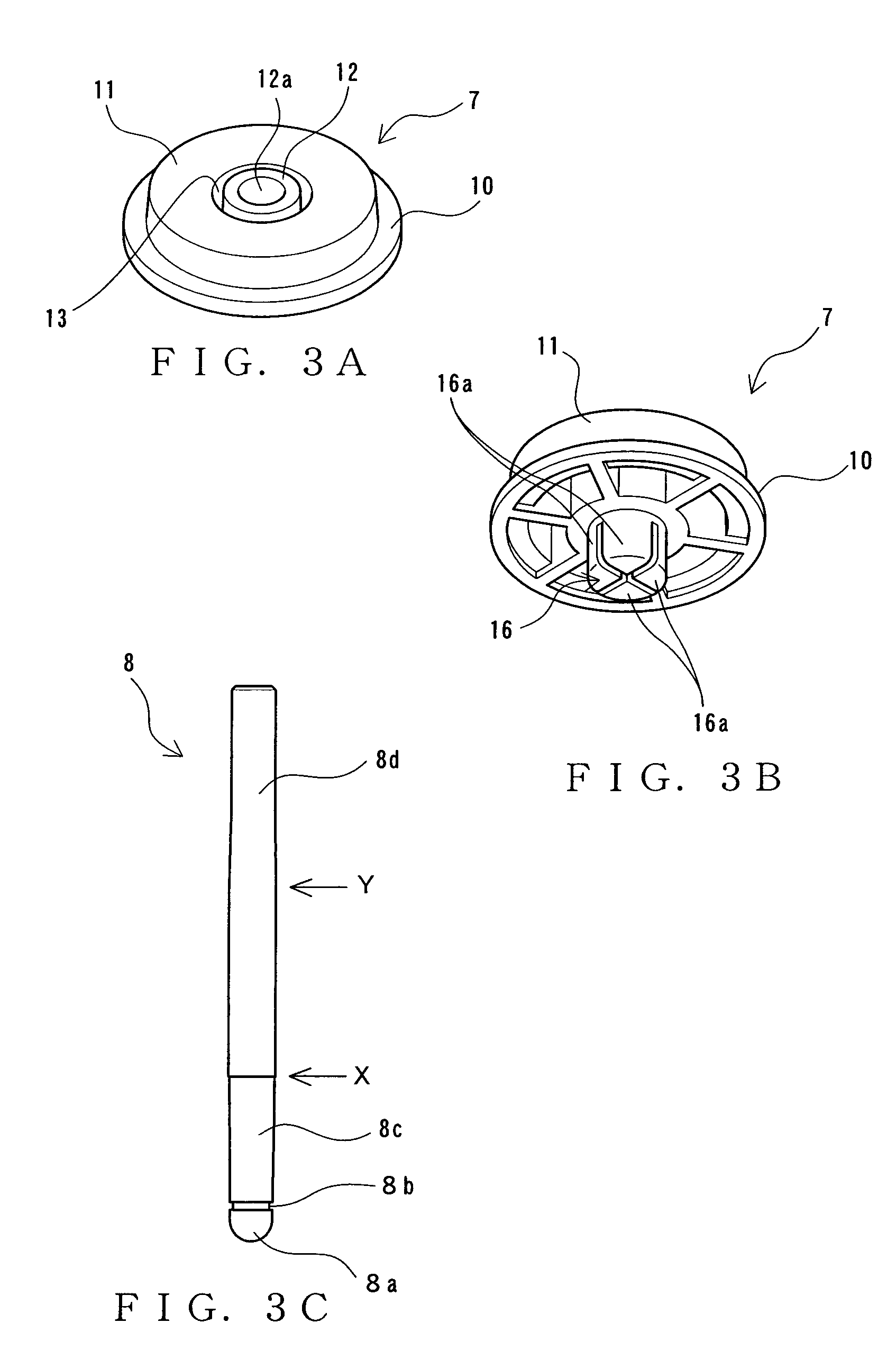
[0026]Each of the thread stands 6 includes a connection member 7, and a spool pin (or rod member) 8. FIG. 3A is an upper perspective view of the connection member 7, FIG. 3B is a lower perspective view of the connection member 7, and FIG. 3C is a side view of the spool pin 8. As shown in FIGS. 3A and 3B, the connection member 7 is an integrally-for...


PUM


Abstract

Connection member integrally includes: a supporting section having a shape adapted to support a predetermined portion of a thread spool of a predetermined shape: a cylindrical portion for fixing a spool pin to the connection member by allowing one end portion of the pin to be inserted therein or thereon; and a fitting portion fittingly engageable with a mounting portion of a thread stand plate. Thus, the connection member and the spool pin are attached together to the thread stand plate with the connection member attached to the mounting portion of the thread stand plate via the fitting portion and the spool pin fitted at the one end portion to the cylindrical portion. The supporting section has a shape adapted to support predetermined portions of thread spools of at least two types having different configurations.

Description

BACKGROUND OF THE INVENTION[0001]The present invention relates to thread stands for holding thread reels or spools, each having an upper thread wound thereon, vertically upright at predetermined positions on a thread stand plate, and more particularly to thread stands for use in embroidery sewing machines and various types of industrial sewing machines.[0002]In not only embroidery sewing machines but also industrial sewing machines, requiring upper threads, a thread stand plate 5 is provided, over a machine head, for vertically supporting a plurality of thread spools 51 each having an upper thread wound thereon as illustrated in FIG. 7. FIG. 7 shows a typical example of a conventionally-known thread stand, where the thread stand plate 5 has a plurality of spool pins 52 disposed vertically thereon as members for holding the thread spools 51 substantially upright at predetermined positions. As illustratively seen in FIG. 8, an umbrella member 53 for preventing undesired shaking moveme...

Claims


Application Information

Patent Timeline
Patent Type & Authority Patents(United States)
IPC IPC(8): D05B43/00D05B35/00
CPCB65H49/16D05B43/00B65H2402/5152B65H2701/31B65H2402/51
Inventor HIRATE, MASAYOSHICHINEN, MINAO
Owner TOKAI IND SEWING MACH CO LTD
Why Eureka
Try Eureka