
3-D imaging system with pre-test module

a 3d imaging and pre-testing technology, applied in the field of 3d imaging systems with pre-testing modules, can solve the problems of expensive system, limited degree of resolution, difficult to keep in synchronization, etc., and achieve the effect of accurate imag

Inactive Publication Date: 2010-09-14
UNIV OF SOUTH FLORIDA
View PDF36 Cites 13 Cited by
  • Summary
  • Abstract
  • Description
  • Claims
  • Application Information

AI Technical Summary

Benefits of technology

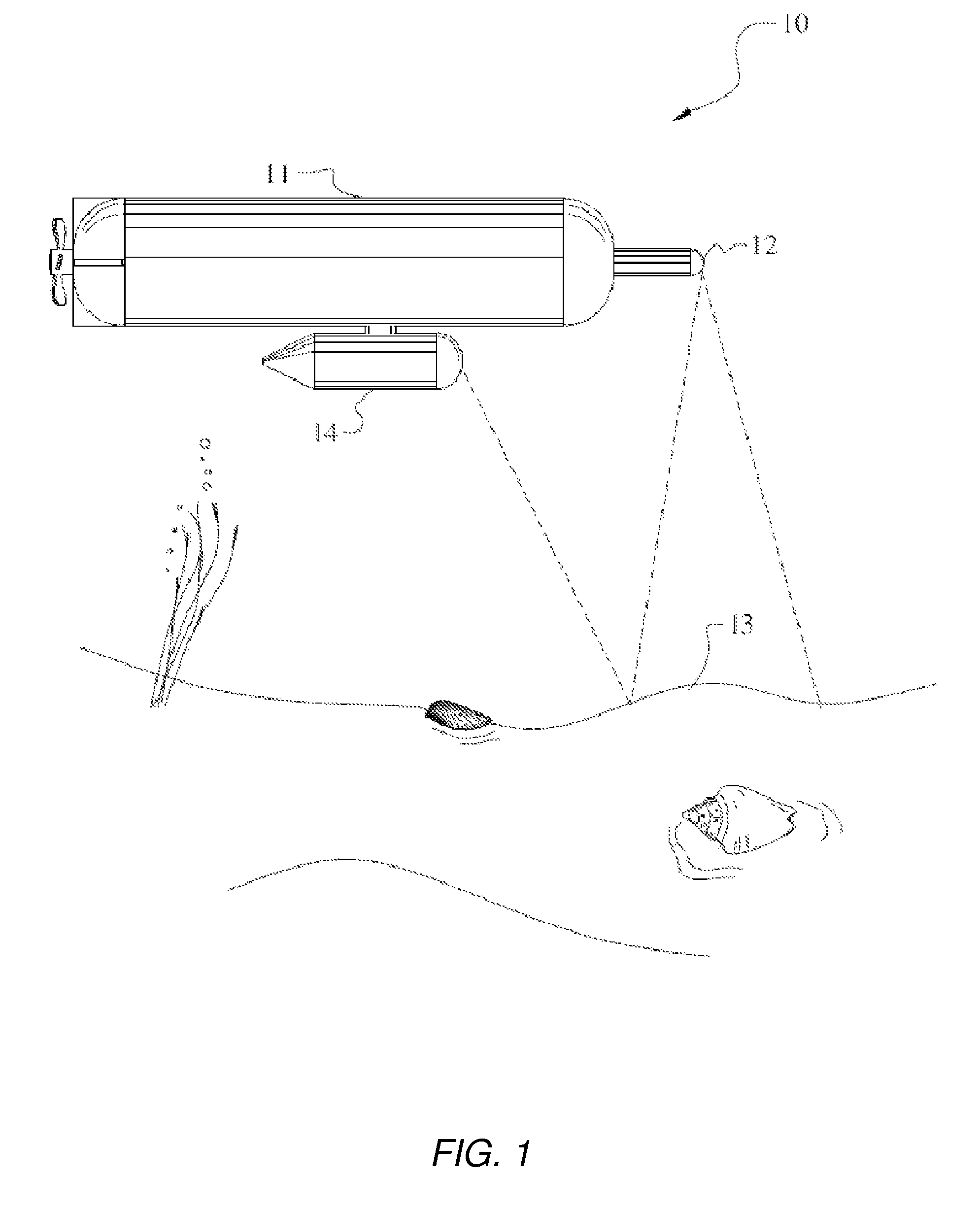
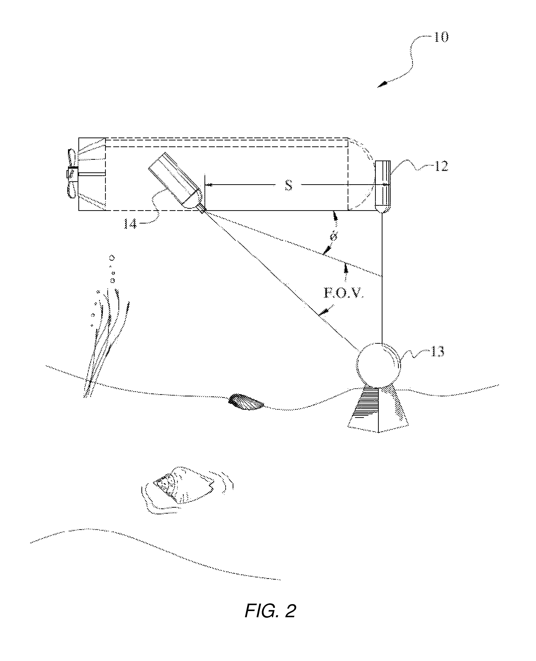
The invention is a system for inspecting the surface of a vessel or ocean floor using a tethered or autonomous vessel designed to accurately image the surface under inspection to locate abnormalities or features of interest. The system includes a platform, an illumination source, a recorder, and a pre-test module. The illumination source can be a laser and can be coupled with a filter to screen out a predetermined wavelength. The recorder can be a still camera, video camera, fluorescent detector, or digital recorder. The platform can be equipped with a navigational device and the recorder can be equipped with a combination of red and green detectors. The invention allows for the accurate inspection of surfaces and the detection of abnormalities or features of interest.

Problems solved by technology

These systems are adapted to generate information over a large scan area, but are limited in degrees of resolution based on the ping rates and distance to the object.
Because of the use of more than one signal to produce the image, Gaer is able to track a moving object, but this system requires a highly sophisticated interfacing of the actual signals and signal generators to provide that information, thus making it a very expensive system and one that, by virtue of the amount of variables to be controlled, is hard to keep in synchronization.
This again is a highly expensive and complicated system to use.
This system, although being lower cost and easier to use than the multi-platform systems, still is incapable of producing high-resolution 3-I) images.
U.S. Pat. No. 5,612,928, also describes a pixel classifying system, but again this system is incapable of producing 3-0 images of photo quality.
This system, since again it uses sonar for imaging, is still limited in the degree of resolution available.
This system again only is capable of location and is not an imaging system per se.
Nothing is reported about the quality of those images and the problems that the video camera solves.
This device is also limited in that it requires a diver to operate the equipment.
Again, no discussion on how the images are enhanced or obtained in sufficient clarity to produce accurate representations of the object under investigation is made.

Method used


Image

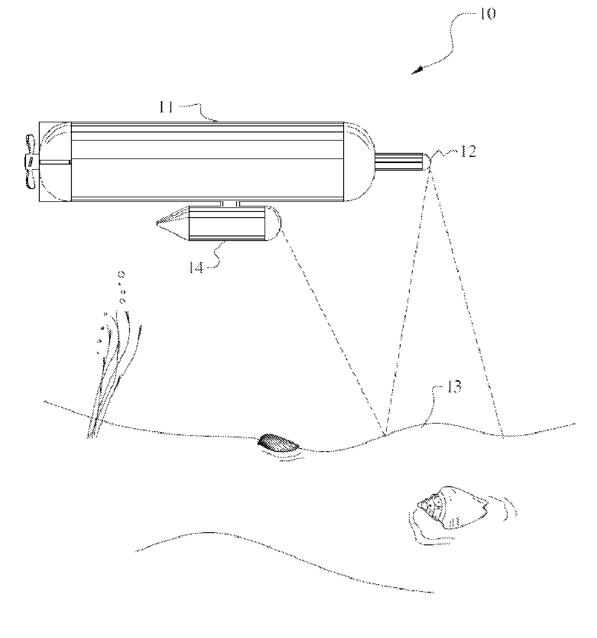
  • 3-D imaging system with pre-test module
  • 3-D imaging system with pre-test module
  • 3-D imaging system with pre-test module

Examples


Embodiment Construction

[0031]In the following detailed description of the preferred embodiments, reference is made to the accompanying drawings, which form a part hereof, and within which are shown by way of illustration specific embodiments by which the invention may be practiced. It is to be understood that other embodiments may be utilized and structural changes may be made without departing from the scope of the invention.

[0032]Therefore it is an advantage of the instant invention to provide an imaging system for underwater profiling that is capable of minute definition.

[0033]Another advantage presented by the instant invention is an imaging system based on non-acoustic imaging.

[0034]It is a further advantage of the invention that an imaging system based on visual imaging that is capable of compensating for turbidity and other conditions deleterious to visual imaging in underwater environments by virtue of a pre-test module.

[0035]It is still a further advantage of the invention that an imaging system ...


PUM


Abstract

A remote 3-D imaging system which uses a novel angular relationship to establish the relationship of the image features to the system, which is displayed by virtue of calculations. In addition to static surfaces, moving surfaces may be studied and corrections due to turbidity and platform position are also easily compensated for. A pre-test module is also included which predicts and has the ability to re-adjust the instrumentation to the test conditions as predicted by a hybrid Monte Carlo model. The instant system may also contain a plurality of sensing systems based on light, including traditional reflective or elastic scattering and novel fluorescent or non elastic scattering still and video imaging systems, including time-gated systems.

Description

CROSS REFERENCE TO RELATED APPLICATION[0001]This application claims priority from U.S. provisional application Ser. No. 60 / 481,795, bearing the same title and with identical inventorship, filed Dec. 15, 2003.STATEMENT OF GOVERNMENT INTEREST[0002]The work that led to this invention has been supported in part by a grant from the Office of Naval Research, Grant Number N00014-01-1-0279. Thus, the United States Government may have certain rights to this invention.BACKGROUND OF THE INVENTION[0003]Interest in the profile of underwater surfaces has grown significantly in the past several decades. Indeed, the ability to map and detect features in the underwater environment have become of interest in the areas of science, resource exploration and national defense, to name a few. This has led to the development of various types of instrumentation for imaging the areas of interest.[0004]One type of imaging system employs the use of sonar and translates the differences in the echo signal to loca...

Claims


Application Information

Patent Timeline
Patent Type & Authority Patents(United States)
IPC IPC(8): G06K9/00G06V10/143
CPCG06K9/00208G06K9/2018G01S17/107G01S17/89G01S17/18G06V20/647G06V10/143
Inventor CARDER, KENDALL L.REINERSMAN, PHILLIP N.
Owner UNIV OF SOUTH FLORIDA
Learn More