Method for optimizing detection of inelastically scattered light from a distant target by measuring the target distance using inelastically scattered light

a technology of inelastically scattered light and distance measurement, which is applied in the direction of material excitation analysis, instruments, measurement devices, etc., can solve the problems of reducing the detection performance, retro-reflecting targets, and reducing the elastic scattered signal, so as to improve the reliability and sensitivity of standoff raman scattering, and simplify the design and operation. , to achieve the effect of maximizing the desired signal

Active Publication Date: 2019-07-16
ALAKAI DEFENSE SYST
View PDF13 Cites 4 Cited by
  • Summary
  • Abstract
  • Description
  • Claims
  • Application Information

AI Technical Summary

Benefits of technology

[0024]Other objects, features, aspects, or advantages of the invention include methods, apparatus, or systems which include one or more of the following.
[0025]It is an object of the invention to simplify the design and operation of a standoff Raman or other optical spectroscopy system by utilizing a distance measurement made using the Raman or other inelastic scattering spectroscopy measurements to control the setup and operation of the Raman or other optical measurement.
[0026]It is another object of the invention to improve the reliability and sensitivity of standoff Raman scattering or other inelastic scattering spectroscopy measurements by utilizing a distance measurement made by the Raman or other optical system to optimize controllable parameters of the standoff Raman or other optical spectroscopy system such as timings and focus distances.
[0027]Aspects of the present invention comprise a method for utilizing the inelastic optical scattering signal from a target and / or from the intermediate media between the sensor and the target to determine the optimal detection system settings to maximize the desired signal from the target, and / or minimize the background signals. A desirable feature is that by using the inelastic scattering signal of the intermediate media rather than the well-known method of using the elastic scattering (reflected light) from the target, the measurement is relatively insensitive to the reflectivity and orientation of the target. Another desirable feature is a reduction in the overall complexity of the system by reducing the need for an additional range finder device as a secondary component or by reducing the performance requirements for such an additional rangefinder. Another desirable feature is improvement of the performance and / or reliability of the detection system by determining the range by using the same components and methodology as the primary system.
[0028]Other aspects of the invention include implementing methodologies as summarized above into apparatus and systems.
[0029]These and other objects, features, aspects, and advantages of the invention will become more apparent with reference to the accompanying specification, drawings, and claims.

Problems solved by technology

One weakness of LIDAR range-finding and object detection is that it requires the target to be retro-reflective, i.e. some portion of the light must elastically scatter (reflect) off the target back to the rangefinder.
Targets with anti-reflective coatings, absorptive coatings, or even transparent targets can degrade the detection performance by reducing the elastic scattered signal.
Another weakness of LIDAR is that measuring target range through an intermediate medium that is partially reflective, such as smoke or fog, significantly complicates the measurement, because these materials retro-reflect a portion of the light back to the receiver, generating signals at times earlier than the signal from the target.
Another weakness of LIDAR is that it can be jammed by a target or nearby object emitting pulsed light at the same wavelength.
However, the challenges for accurate, timely, and practical techniques are many.
Sufficient stand-off interrogation distances (sometimes tens if not hundreds of meters) make it difficult to ensure and know if the excitation energy is optimally interrogating the target and if the light energy collected thereafter is optimally from the target and not from other materials (including the molecules that make up ambient air between detector and target).
This adds a level of complexity and unpredictability.
Raman content is notoriously weak relative to other content in light collected from the target, so it is difficult to extract.
There are several issues with the existing methodologies for determining range.
A fixed range is generally only useful in a controlled laboratory setting as controlling the range precisely is generally not feasible in commercial settings.
Another issue is that by having a secondary range finder device the range finder either has to be bore sighted to the primary laser of the spectroscopy system, which adds additional complexity to the overall system, or the range finder will have a differing line of sight than the primary laser, adding uncertainty to the accuracy of the measurement.
A secondary line of sight introduces the possibility that the range finder will strike a target that is not the actual target of interest and could potentially give the incorrect range to the target reducing the apparent reliability of the system.
This introduces another possible source of error in that the calibration may either be done incorrectly or that there are delays inherent to the system that are not constant which again reduces the overall system accuracy or increases the system complexity.
Yet the competing factors to make them accurate and practical make solutions elusive and unpredictable.
Working at relatively large distances, but at nano- and even pico-second time domains with substantial signal-to-noise, are imposing challenges.

Method used


Image

  • Method for optimizing detection of inelastically scattered light from a distant target by measuring the target distance using inelastically scattered light
  • Method for optimizing detection of inelastically scattered light from a distant target by measuring the target distance using inelastically scattered light
  • Method for optimizing detection of inelastically scattered light from a distant target by measuring the target distance using inelastically scattered light

Examples


Embodiment Construction

4.1 Overview

[0042]For a better understanding of the invention, examples of forms it can take will now be described in detail. It is to be understood, however, that the following examples are neither exclusive nor inclusive of all forms and embodiments the invention can take. Variations obvious to those skilled in the art will be included within the invention, which is defined by the claims.

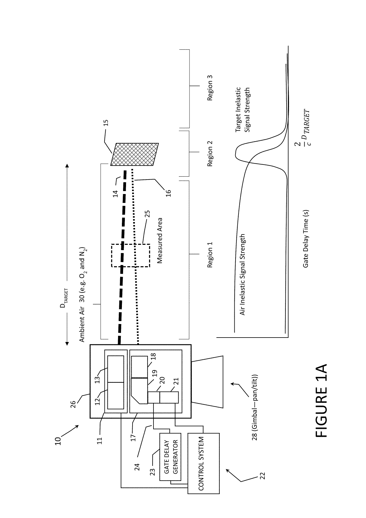
[0043]For instance, the descriptions below will mention certain pulsed UV lasers of indicated characteristics as a target-illuminating source, certain optical arrangements for both focusing the laser towards a target and collecting scattering from the target, certain gate generation techniques for differentiating portions of the collected scattering based on time-of-flight, certain spectrometry components and techniques, and certain spectrometry processing components and techniques; all in the context of aspects of the present invention. It is to be understood that these components and techniques ...


PUM

PropertyMeasurementUnit
energyaaaaaaaaaa
energyaaaaaaaaaa
wavelengthsaaaaaaaaaa

Abstract

The present invention comprises a novel approach for optimizing detection performance of a standoff optical detection system using the inelastic scattering of light from the target and/or inelastic scattering of light from molecules between the light emitting source and the target. This is a useful approach primarily for systems which already employ a pulsed light source, a detector, and a timing mechanism but whose primary function is not the detection of range. Using this methodology removes the need to deploy a secondary device to find range or augments the ability of any included range finder to widen the overall system operating envelope, reliability, and performance.

Description

CROSS-REFERENCE TO RELATED APPLICATIONS[0001]This application claims the benefit of Provisional Application U.S. Ser. No. 62 / 425,652 filed on Nov. 23, 2016, all of which is herein incorporated by reference in its entirety.GOVERNMENT RIGHTS CLAUSE[0002]This invention was made with Government support under contract no. W911NF-14-C-0156 issued by the U.S. Army. The Government has certain rights in the invention.1 BACKGROUND OF THE INVENTION[0003]1.1 Field of the Invention[0004]The present invention is a methodology for optimizing performance of a standoff optical spectroscopy system using measurements of optical inelastic scattering from an intermediate medium between the sensor and target and / or utilizing optical inelastic scattering from the target.[0005]1.2 Related Art[0006]Optical range-finding or LIDAR (light detection and ranging) is a well-known method for measuring distance. An LIDAR range-finder works by emitting pulses of light (typically infrared but visible or ultraviolet a...

Claims


Application Information

Patent Timeline
Patent Type & Authority Patents(United States)
IPC IPC(8): G01N21/65
CPCG01N21/65G01N2201/064G01N2201/061G01S7/4802G01S7/4814G01S7/4816G01S17/88G01S17/18G01N21/49G01S7/4808G01S17/00G01S17/08
Inventor POHL, KENNETH R.NEGLIA, CHRISTOPHER
Owner ALAKAI DEFENSE SYST
Why Eureka
Try Eureka