Image forming apparatus

a technology of image forming apparatus and transfer belt, which is applied in the direction of electrographic process apparatus, digital output to print units, instruments, etc., can solve the problems of significant image quality degradation, increase in the speed of the transfer belt, and increase in so as to reduce color shift and image blurring, increase the cost and size of the apparatus, and reduce the effect of temperatur

Inactive Publication Date: 2010-09-14
CANON KK
View PDF8 Cites 5 Cited by
  • Summary
  • Abstract
  • Description
  • Claims
  • Application Information

AI Technical Summary

Benefits of technology

[0019]The present invention provides an image forming apparatus that can reduce color shift and image blurring caused by increased temperature in the apparatus and form high-quality images without causing an increase in the cost and size of the apparatus.
[0021]According to the present invention, color shift and image blurring caused by increased temperature in the apparatus can be reduced without causing an increase in the cost and size of the apparatus. Thus, high-quality images can be formed.

Problems solved by technology

With the conventional image forming apparatus, however, there may be a case where the inside temperature is increased due to temperature control of a heater incorporated in the fixing unit and / or heating of the drive motors, and the transfer belt drive roller thermally expands due to the increased temperature, causing an increase in the speed of the transfer belt.
In such a case, when toner images of respective colors are transferred in a superposed manner onto a specific position on a transfer material, so-called color shift occurs to cause significant degradation of image quality.
Specifically, since the photosensitive drums and the transfer belt drive roller are controlled to rotate at fixed speeds, the circumferential velocity of the transfer belt drive roller increases as the diameter of the transfer belt drive roller increases due to thermal expansion, and as a result, the speed of the transfer belt increases, which causes color shift.
(1) Although the start positions of image writing for respective colors can be in registration immediately after registration correction, the circumferential velocity of the transfer belt gradually increases, for example, in the case of continuous printing since the temperature in the apparatus further increases, and thus, after completion of printing on a plurality of sheets, the amount of color shift is large.
(2) To solve this problem, for example, registration correction may be carried out each time printing on a predetermined number of sheets is completed, but frequent registration correction would decrease the throughput of the image forming apparatus. In addition, since a registration correcting pattern is formed on the transfer belt during registration correction, the consumption of toners is increased, which causes degradation of cost-efficiency for users.
In this method, however, due to the need for forming the reference mark in advance on the transfer belt, the manufacturing cost of the transfer belt is high, and the apparatus has to be wide so as to ensure a space for the reference mark on the transfer belt.
Such a problem also arises in an image forming apparatus having an intermediate transfer member.
When the speed of the transfer belt increases with an increase in temperature in the apparatus, a difference between the transfer material conveying force exerted by the sheet feed and conveying roller pair and the transfer material conveying force exerted by the transfer belt increases, causing color shift and image blurring.
On the other hand, there is the problem that, when the transfer material conveying force exerted by the transfer belt is greater than the transfer material conveying force exerted by the sheet teed and conveying roller pair, image blurring or color shift occurs at the leading end of the transfer material.

Method used


Image

  • Image forming apparatus
  • Image forming apparatus
  • Image forming apparatus

Examples


first embodiment

[0048]First, a description will now be given of an image forming apparatus according to the present invention.

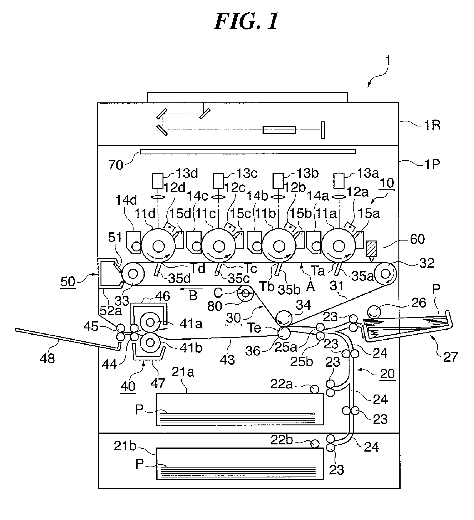
[0049]FIG. 1 is a sectional view showing the essential parts of the image forming apparatus according to the first embodiment. As shown in FIG. 1, the image forming apparatus 1 according to the first embodiment is a color image forming apparatus comprised of a plurality of image forming sections arranged side by side.

[0050]The image forming apparatus 1 is of an electrophotographic type and comprised of an optical system 1R and an image output section 1P. The optical system 1R reads images on originals, and the image output section 1P forms images on transfer materials P based on image information read by the optical system 1R. The image output section 1P is comprised mainly of an image forming section 10, a sheet feed unit 20, an intermediate transfer unit 30, a fixing unit 40, and a controller including a control board 70. In the image forming section 10, four stations iden...

third embodiment

[0151]Next, a description will be given of an image forming apparatus according to the present invention.

[0152]The image forming apparatus according to the third embodiment differs from the image forming apparatus according to the first embodiment described above in the motor speed control process and the movement control process. Specifically, the relative speed and shift amount of the intermediate transfer belt are not computed using pattern matching of images as in the first embodiment described above, but are computed using a centroid computation method. In the following description, component elements corresponding to those in the first embodiment described above are denoted by the same reference numerals and description thereof is omitted. Only points of differences will be described below.

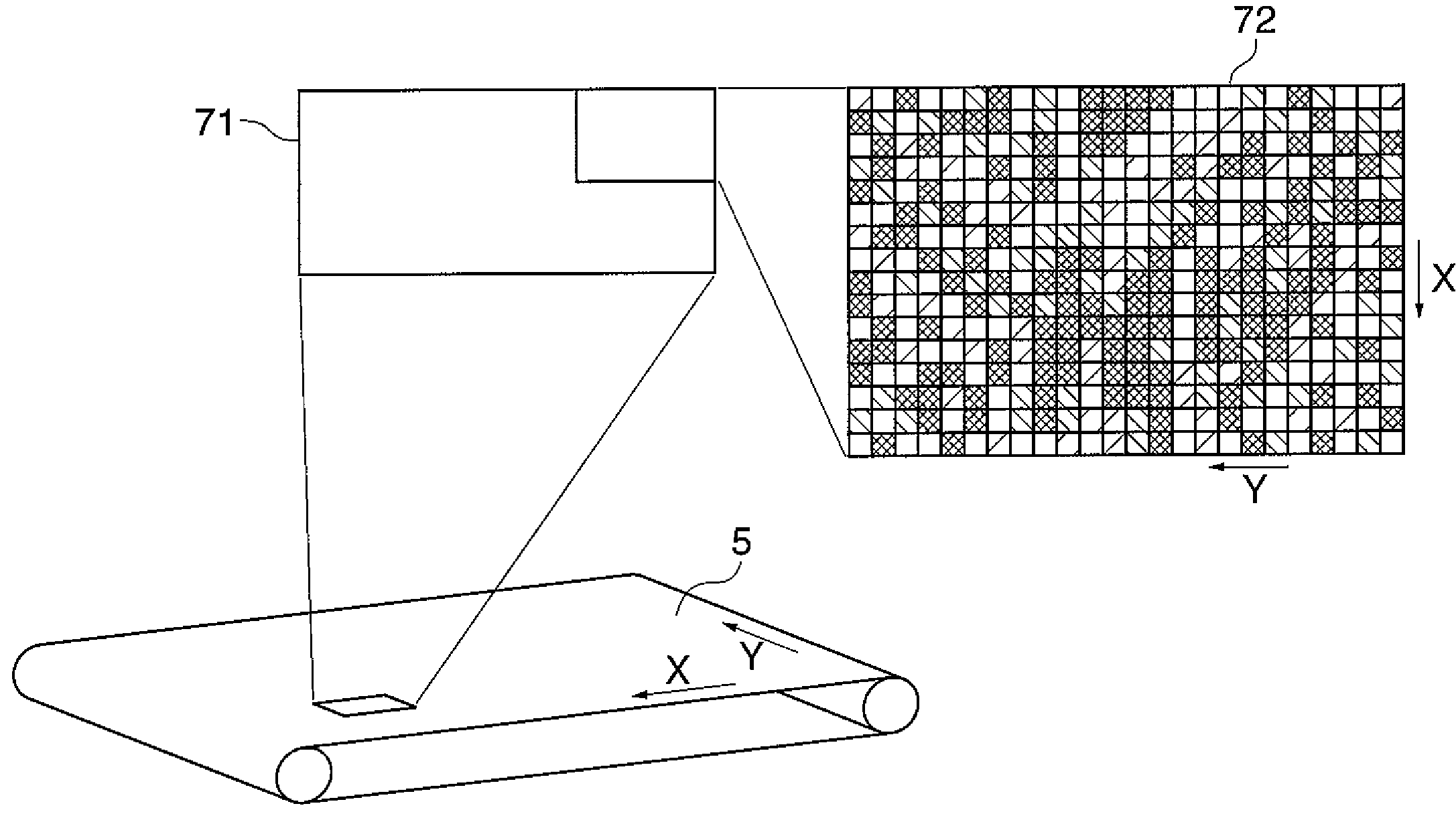
[0153]FIGS. 20A and 20B are diagrams showing respective surface images 161 and 162 obtained as a result of binarization of surface images of the intermediate transfer belt 31 read by the CMO...


PUM


Abstract

An image forming apparatus which can reduce color shift and image blurring caused by increased temperature in the apparatus and form high-quality images without causing an increase in the cost and size of the apparatus. An image sensor unit reads surface patterns of an intermediate transfer belt. A digital signal processor (DSP) controls the movement of the belt in a transverse direction perpendicular to a moving direction thereof based on the surface patterns of the belt read by the image sensor unit.

Description

BACKGROUND OF THE INVENTION[0001]1. Field of the Invention[0002]The present invention relates to an image forming apparatus such as a color copying machine or a color laser printer.[0003]2. Description of the Related Art[0004]As shown in FIG. 24, an image forming apparatus 1001 which is a conventional image forming apparatus is comprised of a transfer belt 1005 as a transfer material bearing member that carries and conveys transfer materials P. In the image forming apparatus 1001, process cartridges (hereinafter merely referred to as the cartridges) for yellow (Y), magenta (M), cyan (C), and black (Bk) are arranged in tandem along a transfer material bearing surface of the transfer belt 1005. Above the cartridges 1014 to 1017, optical units 1018, 1019, 1020, and 1021 are arranged in association with the respective cartridges 1014 to 1017. Below the cartridges 1014 to 1017, transfer rollers 1010, 1011, 1012, and 1013 associated with respective photosensitive drums 1006, 1007, 1008, a...

Claims


Application Information

Patent Timeline
Patent Type & Authority Patents(United States)
IPC IPC(8): G03G15/01
CPCG03G15/0131G03G15/161G03G2215/00156G03G2215/0016G03G2215/0119G03G2215/0129G03G2215/0141G03G2215/0158G03G15/14G06F3/12
Inventor KINOSHITA, HIDEHIKOYAMAGUCHI, JUNNAKAGAWA, ATSUSHIMORIYA, MASAAKIMIZUNO, MANABU
Owner CANON KK
Why Eureka
Try Eureka