Optical sight

Inactive Publication Date: 2010-09-21
GS DEVMENT
View PDF32 Cites 28 Cited by
  • Summary
  • Abstract
  • Description
  • Claims
  • Application Information

AI Technical Summary

Benefits of technology

[0012]The invention yields a significant increase of the overall efficiency of the sight because the laser diode has an electrical-to-(useful)optical efficiency, i.e. the efficiency in converting electric energy into useful optical energy which is used to produce the light seen by the user, which is considerably higher than the electrical-to-(useful)optical efficiency of a conventional LED as used in existing sights. Moreover, if the la

Problems solved by technology

The main problem with these sights is low battery life (approximately four hours of continuous use at the brightest spot intensity).
This can lead to various practical problems especially if the user is in some remote location and batteries are not readily available.
This adds

Method used


Image

  • Optical sight
  • Optical sight
  • Optical sight

Examples


Example

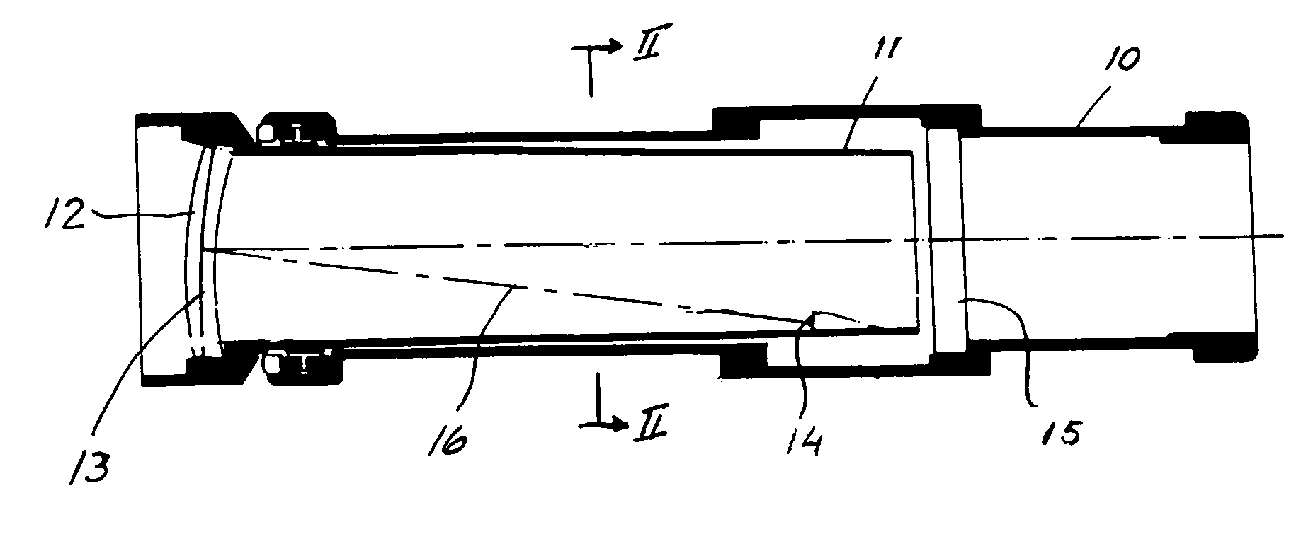
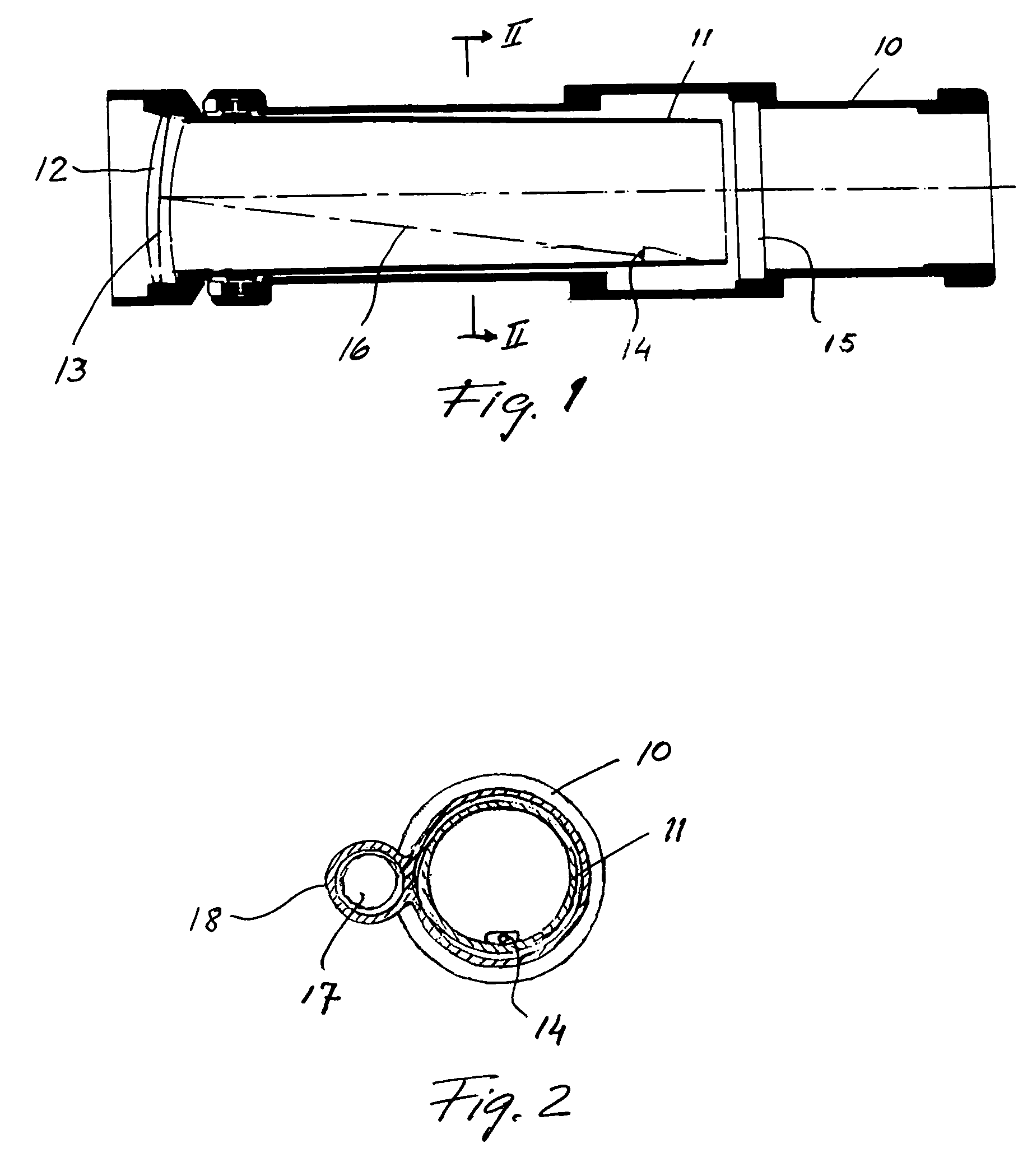
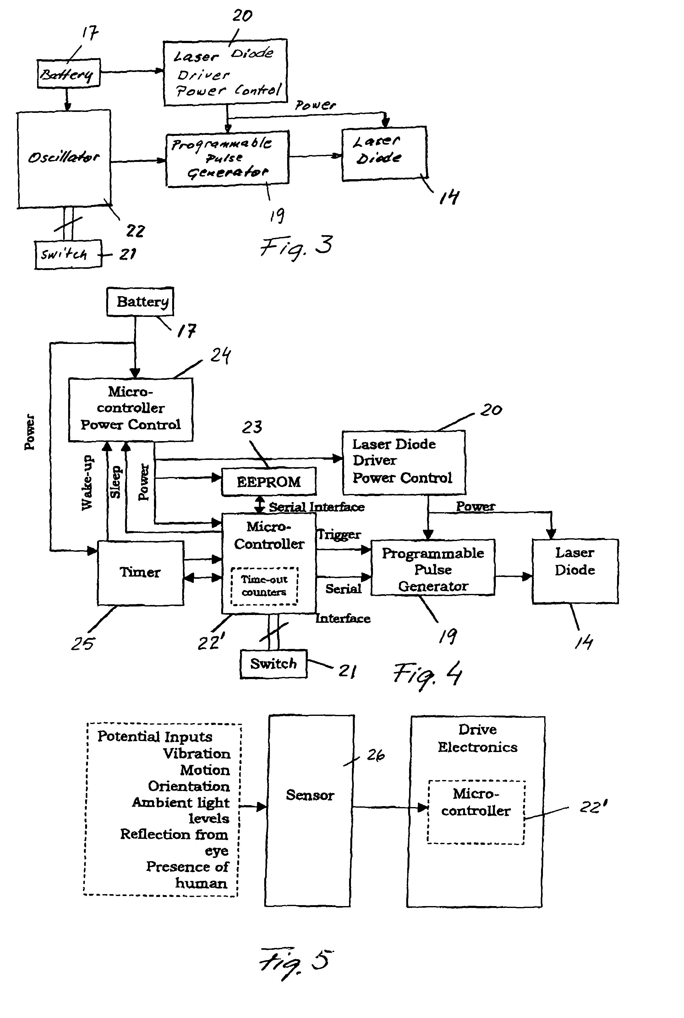
[0019]The weapon sight disclosed in FIG. 1 comprises a light tunnel formed by an outer tube 10 to be fastened to the barrel of a weapon on which the sight shall be used, and an inner tube 11 which is mounted in the outer tube at one end and is fixed at the other end by adjustment means allowing adjustment of the longitudinal axis of the inner tube in relation to the longitudinal axis of the outer tube as is necessary in order to adapt the sight to the weapon on which it is used. In the one end of the inner tube a double lens 12 is provided having a layer 13 between the lenses, the reflecting red light. Inside the inner tube a light source 14 comprising a laser diode is mounted which projects a beam of red light on the layer 13 which reflects the light beam through a face-ground glass plate 15 having an anti-reflexion layer on the side thereof facing the right end of the light tunnel. The light path is indicated by a dot-and-dash line 16 in FIG. 1. The laser diode is energised via el...


PUM


Abstract

An optical sight comprises an elongate housing defining a light channel. A lens is provided at one end of the light channel and has a partially reflecting surface. A laser diode is energised by a pulsating electric current delivered by a battery powered energising circuit, and the energised laser diode emits light towards the reflecting surface to produce a light spot by direct imaging of the laser diode on the surface. The light spot shall be superimposed on the target when sighting through the light channel from the other end thereof.

Description

BACKGROUND OF THE INVENTION[0001]1. Field of the Invention[0002]The invention relates to an optical sight used for example on a hunting weapon such as a hunting gun. The invention more particularly relates to a sight in which a light source creates a light spot which is superimposed on a target which is viewed through the sight.[0003]2. Description of Related Art[0004]Weapon sights comprising a light channel, a lens at one end of the light channel, having a partially reflecting surface, a light emitting diode (LED), and a battery for energising the light source have been available for approximately 20 years. In these sights, the energised LED emits light towards the reflecting surface of the lens to produce an image of a light spot which can be superimposed on a target when sighting through the light channel from the other end thereof. The intensity of the light spot is varied by altering the drive current of the LED.[0005]The main problem with these sights is low battery life (appr...

Claims


Application Information

Patent Timeline
IPC IPC(8): F41G1/34F41G1/30G02B23/14
CPCF41G1/30G02B23/14Y10S33/21
Inventor SCOTT, VALERIE ANNEGREEN, ALAN EDWARDMORRISON, EUAN
Owner GS DEVMENT
Why Eureka
Try Eureka