Portable rotary chipper apparatus

a chipper and portable technology, applied in the direction of gas current separation, grain treatment, potato planters, etc., can solve the problems of increasing the overall cost of the chipping operation, affecting the chipping operation, so as to reduce the size of the chipped material engaged, the effect of cutting the siz

Inactive Publication Date: 2010-09-21
TORO CO THE
View PDF19 Cites 20 Cited by
  • Summary
  • Abstract
  • Description
  • Claims
  • Application Information

AI Technical Summary

Benefits of technology

[0007]At least two shredder / detanglers are secured to the rear face of the disc in diametrically opposed relation relative to each other. Each shredder / detangler includes a base and at least three generally planar and substantially identical paddles arranged in spaced and generally parallel relation relative to each other. Each paddle extends from the base at a predetermined angle and away from the rear face of the chipping disc such that, upon rotation of the disc within said housing, the paddles induce an air flow through the slots in the disc whereby drawing chipped materials through the slots toward the rear side of the disc. Each paddle also has a continuous elongated linear cutting edge for impacting with and further reducing the size of the material engaged by the paddles. Each shredder / detangler further includes an impeller at a distal end of the base for assisting in moving the chipped material toward and out through the discharge chute from the housing.
[0011]The chipping disc is connected to a drive shaft for rotation about an axis of rotation and has a peripheral edge arranged adjacent to the peripheral wall of the housing chamber along with front and rear faces with a series of slots extending through the disc whereby allowing chipped materials to pass from a front side to a rear side of the disc. A knife, on the front face of the disc in proximate relation relative to each slot, is provided for reducing and forming chips from the materials fed into the inlet of the chipper apparatus. Two shredder / detanglers are fixed to the rear face of the disc in diametrically opposed relation relative to each other. Each shredder / detangler includes a base and at least three generally planar and substantially identical paddles arranged in spaced and generally parallel relation relative to each other. The paddles on each shredder / detangler extend from the base at an angle and project away from the rear face of the chipping disc such that, upon rotation of the disc within the housing, the paddles induce an air flow through the slots in the disc whereby drawing chipped materials through the slots toward the rear side of the disc. Each paddle has a continuous elongated linear cutting edge for impacting with and further reducing the size of the chipped material engaged by the paddles. Each shredder / detangler further includes an impeller at a distal end of the base for assisting in moving the chipped material toward and out through the discharge chute from the housing.
[0014]According to another aspect, there is provided a chipping disc for a portable rotary chipper apparatus. The chipping disc has front and rear faces with a series of slots extending through the disc. A knife is fixed to the front face of the disc in proximate relation relative to each slot. At least two shredder / detanglers are fixed to the rear face of the disc. Each shredder / detangler includes a base and at least three generally planar and substantially identical paddles arranged in spaced and generally parallel relation relative to each other. The paddles extend from the base at an angle and projects away from the rear face of the chipping disc. The paddles on each shredder / detangler have a continuous elongated linear cutting edge for impacting with and further reducing and cutting the size of the chipped material engaged by the paddles. Each shredder / detangler further includes an impeller at a distal end of the base.

Problems solved by technology

As the disc rotates, some of these materials tend to move toward the center of the rotary disc and can become entangled with the shaft about which the disc rotates.
Of course, a buildup of these entangled materials about the rotating disc shaft can cause both significant and costly damages to the chipper apparatus.
This downtime adds to the overall cost of the chipping operation.

Method used


Image

  • Portable rotary chipper apparatus
  • Portable rotary chipper apparatus
  • Portable rotary chipper apparatus

Examples


Embodiment Construction

[0029]While the present invention is susceptible of embodiment in multiple forms, there is shown in the drawings and will hereinafter be described a preferred embodiment, with the understanding the present disclosure is sets forth an exemplification of the invention which is not intended to limit the invention disclosure to the specific embodiment illustrated and described.

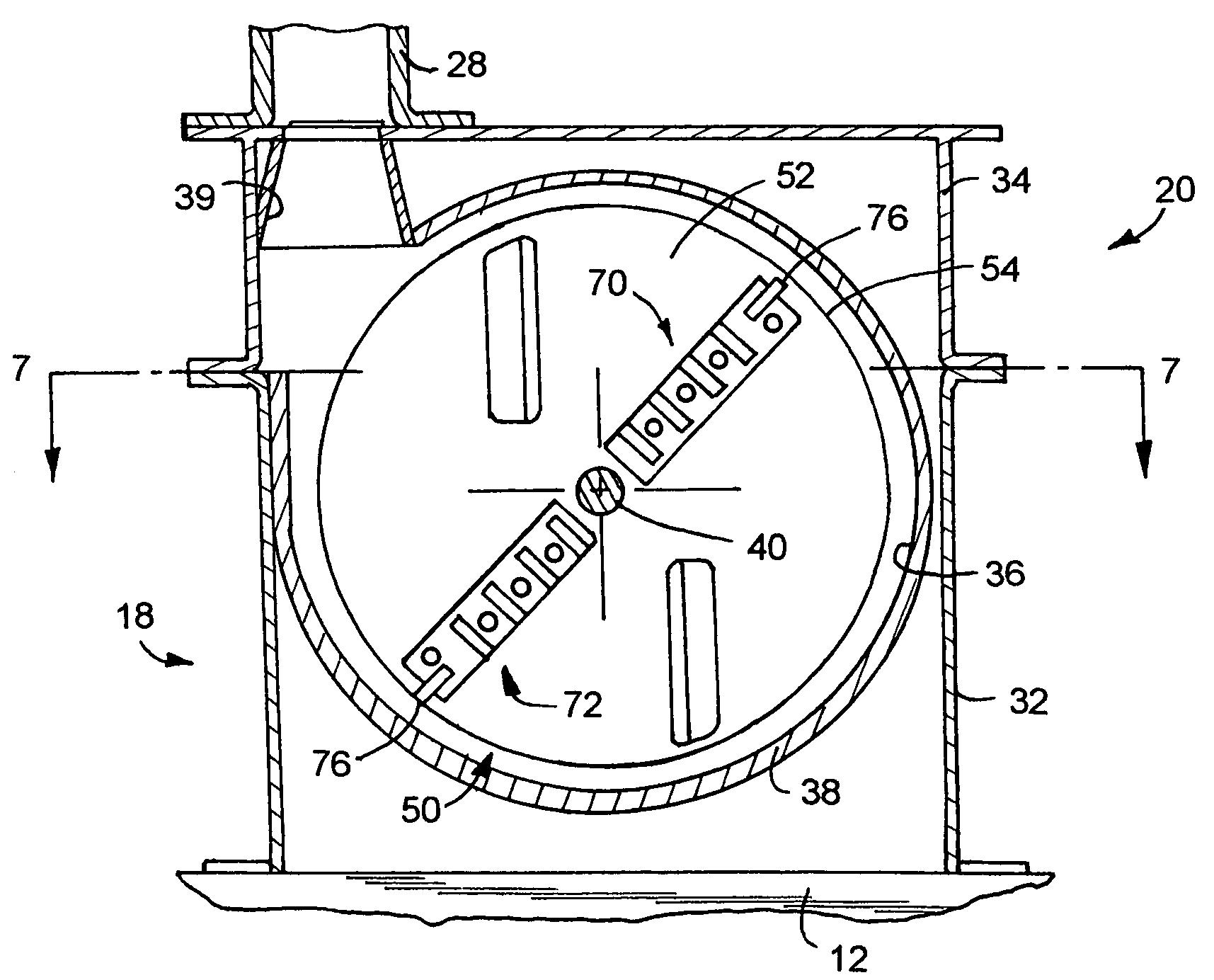
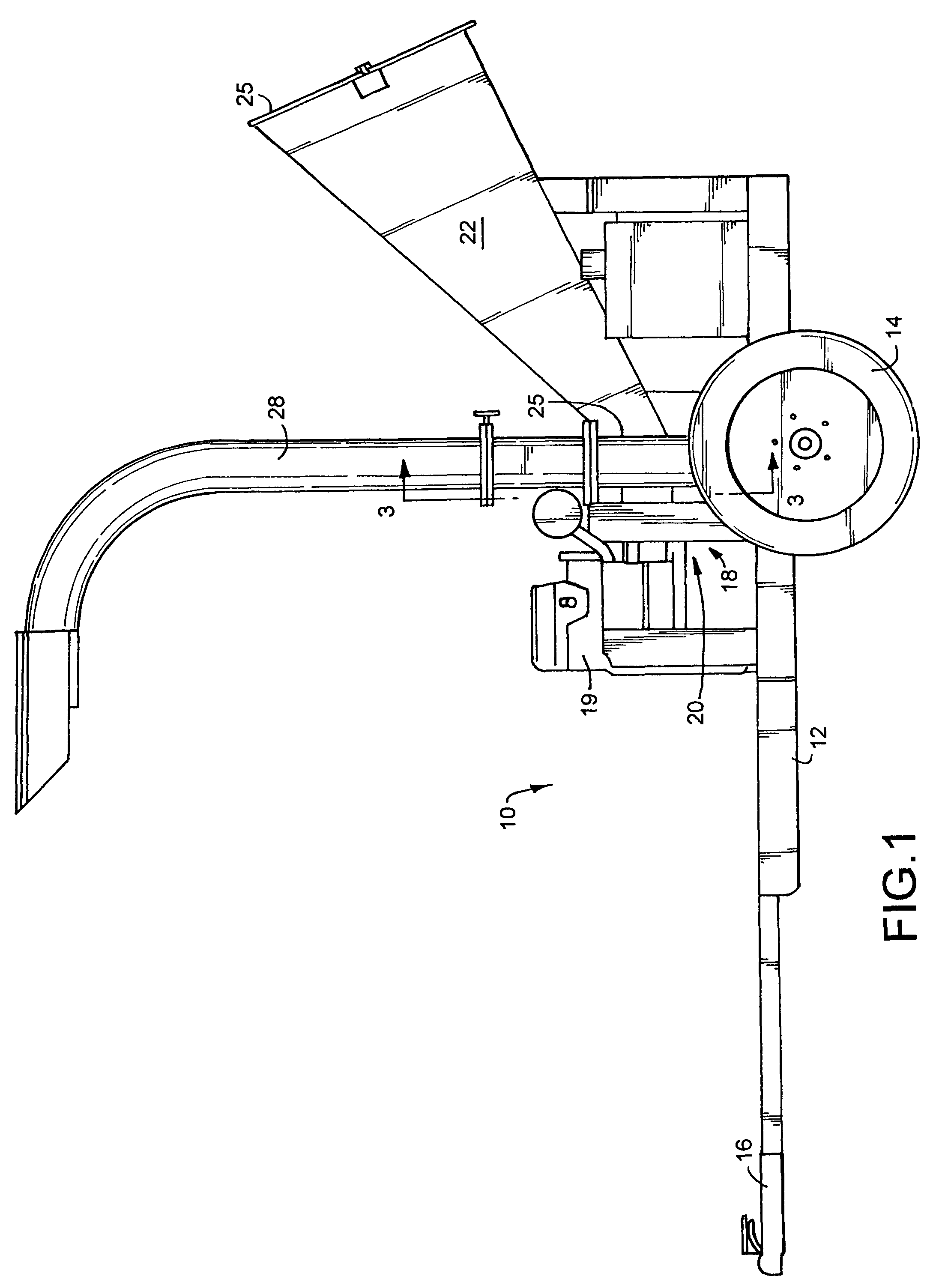
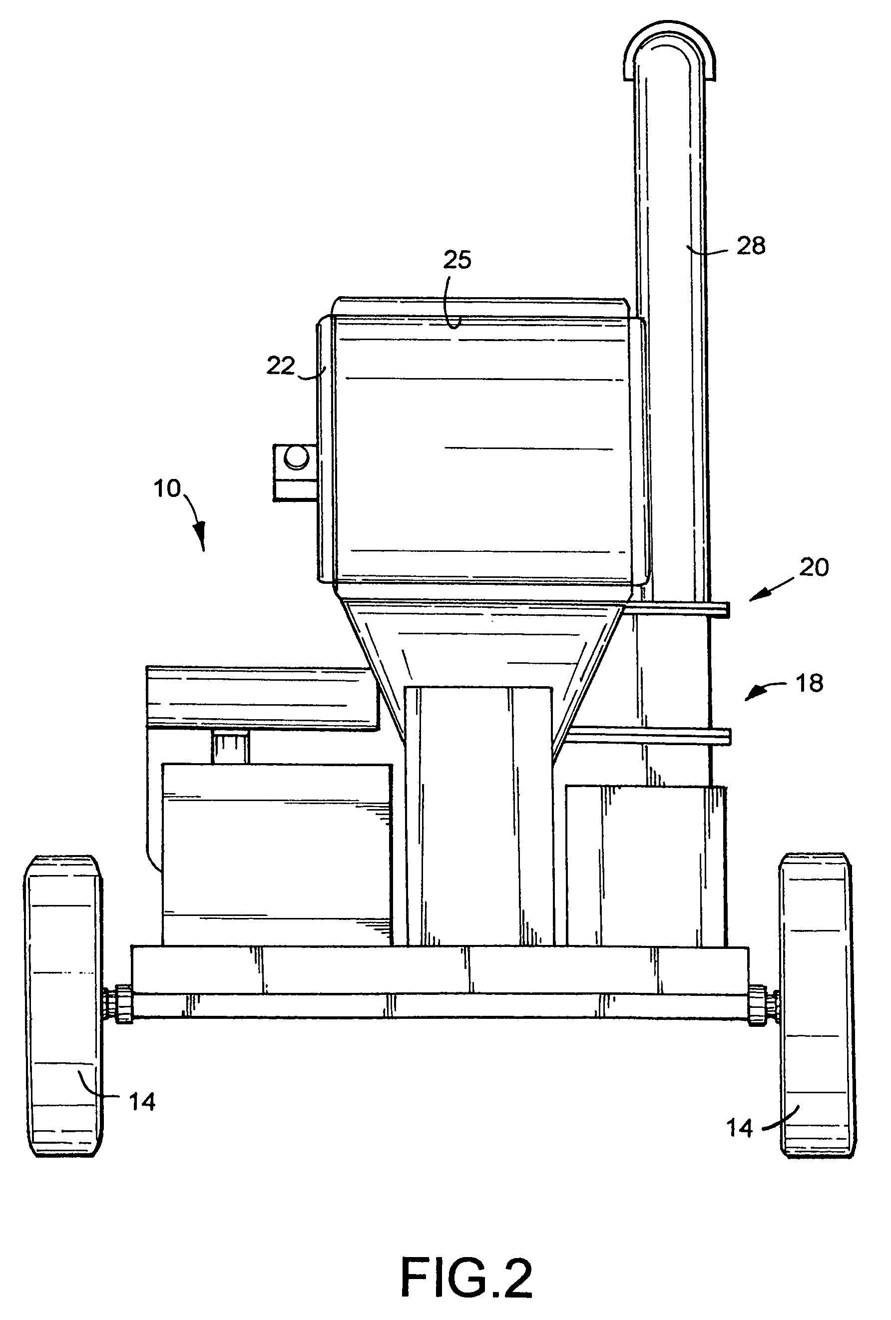
[0030]Referring now to the drawings, wherein like reference numerals indicate like parts throughout the several views, there is shown in FIG. 1 one embodiment of a portable chipper apparatus, generally identified by reference numeral 10, and which includes a rigid frame 12 which is supported for movement toward a rear end thereof by a transverse axle and a pair of wheels 14. A pulling tongue and hitch 16 is arranged toward an opposite end of the frame 12. As such, the chipper apparatus 10 can be readily pulled behind a truck, automobile or tractor. The chipper apparatus 10 further includes a chipper assembly carri...


PUM


Abstract

A portable chipper apparatus having a chipping disc with front and rear faces and a series of slots extending through the disc. A knife is arranged on the front face of the disc in proximate relation relative to each slot. At least two shredder / detanglers are secured to the rear face of the disc. Each shredder / detangler includes a base and at least three generally planar and substantially identical paddles arranged in spaced and generally parallel relation relative to each other. The paddles extend from the base at an angle and projects away from the rear face of the chipping disc. The paddles on each shredder / detangler have a continuous elongated linear cutting edge for impacting with and further reducing and cutting the size of the chipped material engaged by the paddles. Each shredder / detangler further includes an impeller at a distal end of the base.

Description

FIELD OF THE INVENTION DISCLOSURE[0001]This invention disclosure relates to a portable rotary chipper apparatus for reducing materials received thereby into smaller particulate matter or chips.BACKGROUND OF THE DISCLOSURE[0002]Many industrial, commercial and household applications require the breaking up of relative large objects into smaller pieces. The reduction process is variously referred to as cutting, chipping, shredding, mulching, or grinding depending in part on the size of the end product. Chipping is historically accomplished by a rotatably driven disc which produces particulate matter or chips ranging from about ¾ inches and above. Some chippers have been designed which are portable and are capable of processing at least small branches into wood chips which can then be gathered at the site of the tree trimming operation or can be distributed on the ground whereupon the chips will naturally decay without causing environmental pollution.[0003]The rotatably driven disc is t...

Claims


Application Information

Patent Timeline
Patent Type & Authority Patents(United States)
IPC IPC(8): B02C19/00
CPCA01G3/002B02C18/083B02C2201/066
Inventor CORNELIUS, JAMES A.
Owner TORO CO THE
Why Eureka
Try Eureka