Vehicle stabilizer system

a technology of stabilizer and stabilizer body, which is applied in the direction of vehicle springs, interconnection systems, resilient suspensions, etc., can solve the problems of increasing the load on the motor, affecting the practical use of the stabilizer, and reducing the efficiency of the stabilizer, so as to reduce the electric power, reduce the negative efficiency of the actuator, and reduce the negative effect of the negative effect of the actuator

Inactive Publication Date: 2010-09-21
TOYOTA JIDOSHA KK
View PDF7 Cites 14 Cited by
  • Summary
  • Abstract
  • Description
  • Claims
  • Application Information

AI Technical Summary

Benefits of technology

[0006]The stabilizer system constructed according to the invention can be arranged such that the negative efficiency of the actuator is relatively low when the direction of the force of the motor causes a stabilizing force to force a wheel and a body of the vehicle in one of a direction (hereinafter referred to as “bound direction” where appropriate) toward each other and another direction (hereinafter referred to as “rebound direction” where appropriate) away from each other, and such that the negative efficiency is relatively high when the direction of the force of the motor causes the stabilizing force to force the wheel and the body of the vehicle in the other of the bound direction and the rebound direction. This arrangement makes it possible to reduce an electric power required to maintain a height of the vehicle body against an external force forcing the wheel and the body in the above-described other of the bound and rebound directions. That is, where the stabilizer system has a function of adjusting the height of the vehicle body, the above-described advantageous arrangement makes it possible to reduce a load imposed on the motor and accordingly to reduce the electric power consumed in the system.Modes of the Invention
[0007]There will be described various modes of the invention deemed to contain claimable features for which protection is sought. Each of these modes of the invention is numbered like the appended claims and depends from the other mode or modes, where appropriate, for easier understanding of the technical features disclosed in the present specification. It is to be understood that the present invention is not limited to the technical features or any combinations thereof which will be described, and shall be constructed in the light of the following descriptions of the various modes and preferred embodiments of the invention. It is to be further understood that a plurality of elements or features included in any one of the following modes of the invention are not necessarily provided all together, and that the invention may be embodied with selected at least one of the elements or features described with respect to the same mode. It is to be still further understood that a plurality of elements or features included in any one of the following modes of the invention may be combined with at least one additional element or feature in the light of the following descriptions of the various modes and the preferred embodiments of the invention, and that the invention may be embodied with such a possible combination with respect to the same mode.
[0008](1) A stabilizer system for a vehicle, comprising: (a) a stabilizer bar including (a-1) a torsion bar portion, and (a-2) an arm portion that extends in a direction not parallel to the torsion bar portion, from the torsion bar portion toward a wheel of the vehicle; and (b) an actuator including (b-1) a motor, and (b-2) a speed reducer that reduces a speed of the motor while transmitting a force of the motor to the torsion bar portion of the stabilizer bar, wherein the stabilizer bar generates a stabilizing force which is dependent on a reaction that is generated as a result of torsion of the torsion bar portion, and which forces the wheel and the body of the vehicle in a selected one of a direction toward each other and a direction away from each other, wherein the actuator allows the stabilizer bar to generate the stabilizing force whose magnitude is dependent on a magnitude of the force of the motor and is changeable depending on an amount of rotation of the torsion bar portion, and wherein the actuator includes an actuator-efficiency changing mechanism changing a negative efficiency of the actuator, depending on a direction of the force of the motor, the reverse efficiency corresponding to a ratio of the magnitude of the rational force of the motor, minimally required to inhibit the motor from being moved by an external force that acts on the stabilizer bar, to an magnitude of the external force.
[0009]The term “negative efficiency” recited in this mode (1) may be interpreted to correspond to a parameter indicative of the magnitude of the force (e.g., torque or rotational force) of the motor minimally required to inhibit the motion (e.g., rotation) of the motor that could be caused by the external force applied to the actuator, namely, the external force acting on the stabilizing bar and generated due to various factors (such as irregularity of road surface, body roll, pitch, bounce, static load of the vehicle body, and elasticity of suspension spring interposed between the wheel and vehicle body). A low value of the negative efficiency indicates that the motor is hard to be moved by the external force. The direction of the force of the motor (e.g., a forward direction and a reverse direction of the motor) is arranged to correspond to the direction of the stabilizing force, depending on which the wheel and the body of the vehicle are forced by the stabilizing force in a selected one of the direction toward each other and the direction away from each other. Further, the stabilizing force serves as a reaction that is a force opposite to the external force exerted on the stabilizer bar. Therefore, in the stabilizer system defined in this mode (1), owing to the provision of the actuator-efficiency changing mechanism, the magnitude of the force of the motor minimally required to inhibit the motion of the motor, is made different depending upon whether the external force forces the wheel and the body in the bound or rebound direction. This arrangement makes it possible to reduce the magnitude of the force of the motor that is to act in a predetermined direction, i.e., a direction causing the stabilizing force to force the wheel and the body in a selected one of the bound and rebound directions.
[0010]The stabilizer system defined in this mode (1) can be advantageously used for adjusting the height of the vehicle body. When the height of the body is intended to be maintained by the force of the motor acting in the above-described predetermined direction, it is possible to maintain the body height with a reduced load imposed on the motor and a reduced electric power consumed by the motor. That is, in the present stabilizer system, the body-height adjusting function can be satisfactorily established by the actuator that is relatively small-sized to enable the electric power consumption to be remarkably reduced.
[0011](2) The stabilizer system according to mode (1), wherein the actuator-efficiency changing mechanism is provided by a construction of the speed reducer by which an amount of loss in transmission of the force of the motor to the torsion bar portion is changed depending on the direction of the force of the motor.

Problems solved by technology

This results in increase of a load imposed on the motor.
Further, where the supplied electric power (hereinafter referred to as “body-height maintaining electric power” where appropriate) has to be large, this arrangement is disadvantageous from a point of view of electric power saving.
Such disadvantages are factors impeding application of the stabilizer system to adjustment of height of the vehicle body, namely, impeding a practical use of the stabilizer system having the function of adjusting height of the vehicle body.

Method used


Image

  • Vehicle stabilizer system
  • Vehicle stabilizer system
  • Vehicle stabilizer system

Examples


first embodiment

(A) First Embodiment

Construction and Function of Stabilizer System

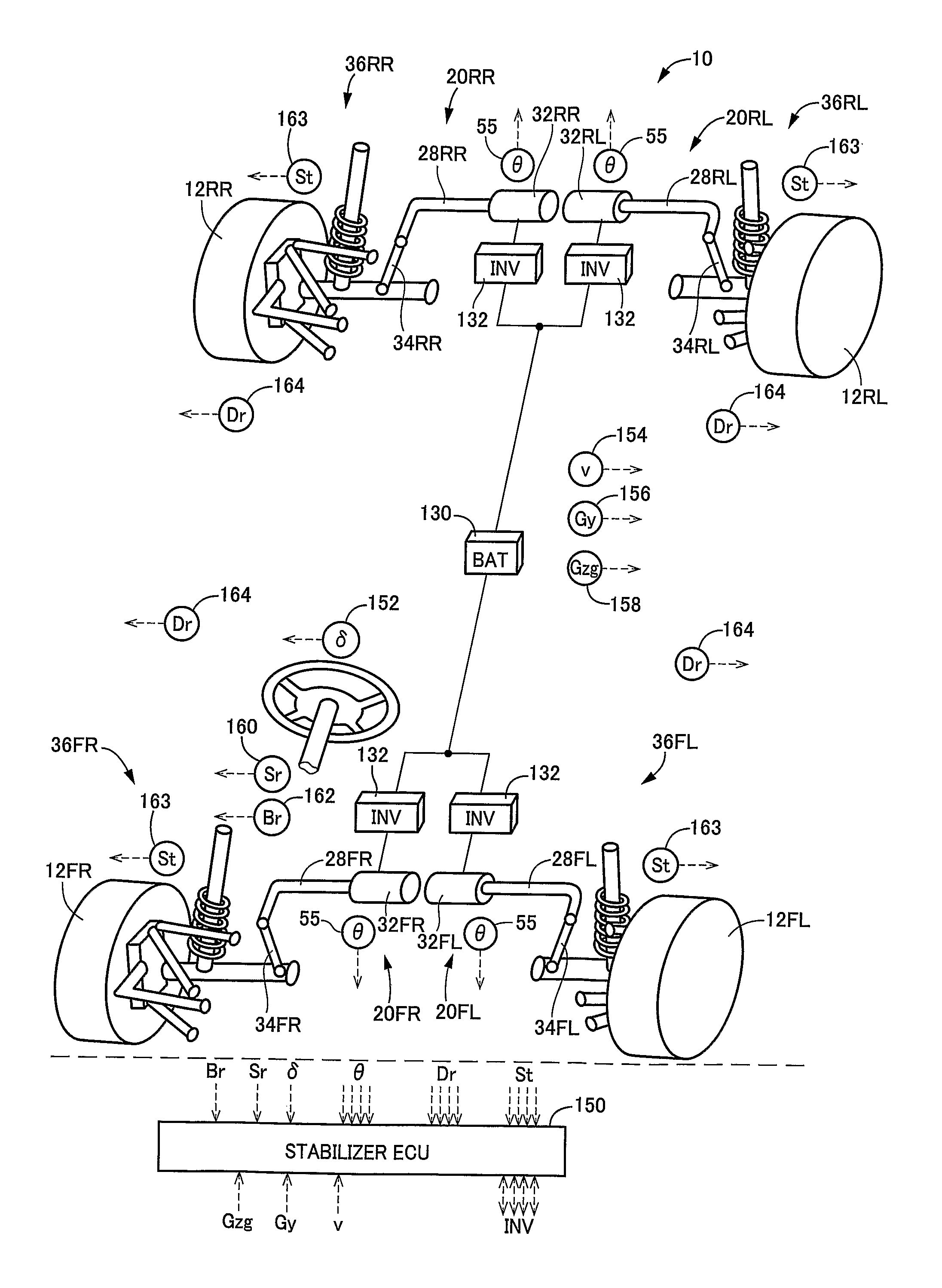
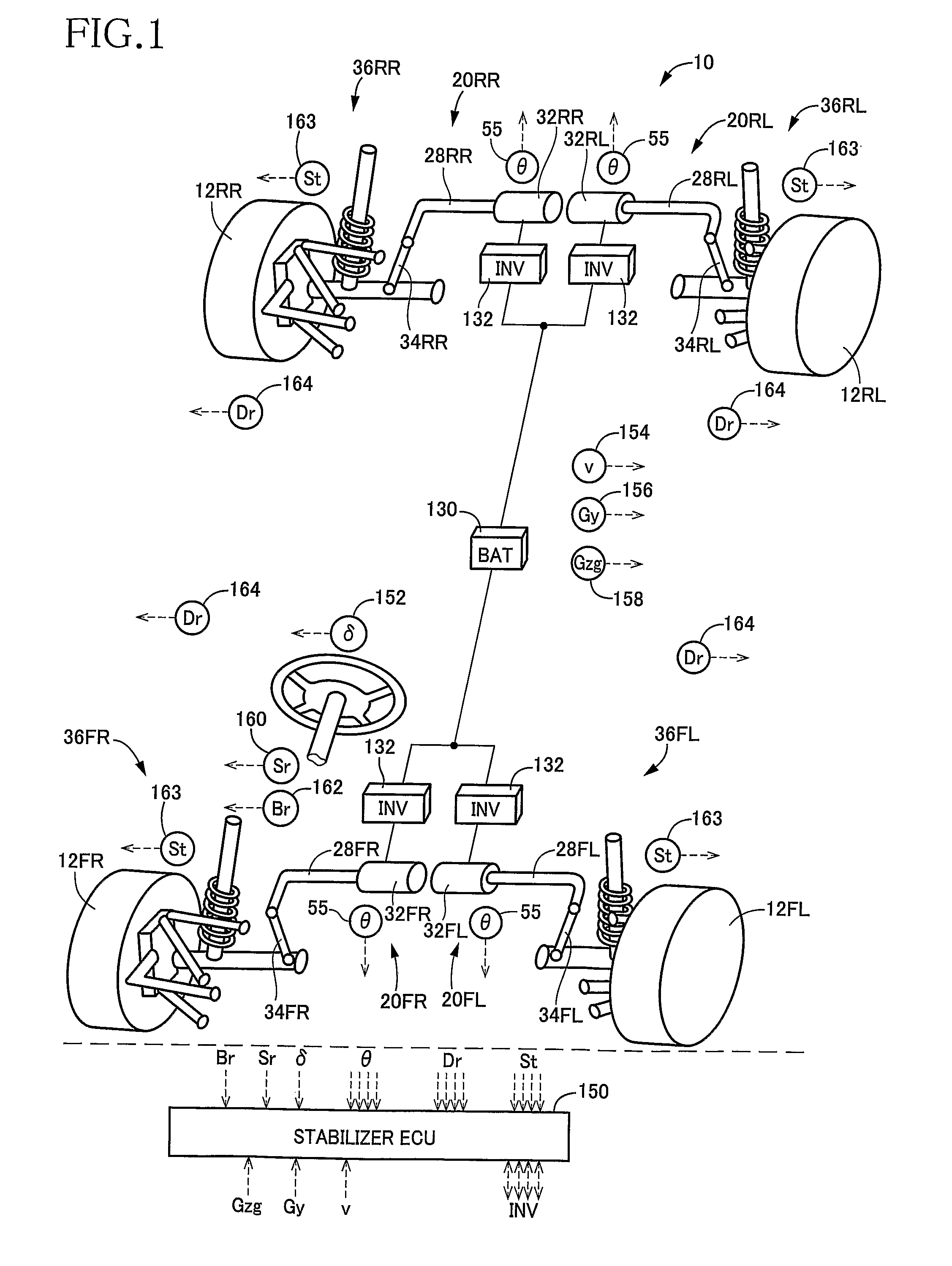
[0045]FIG. 1 schematically shows a vehicle stabilizer system 10 constructed according to a first embodiment of the invention. The stabilizer system 10 includes four stabilizer devices 20 provided for respective four wheels (i.e., front right, front left, rear right and rear left wheels) 12. Each of the stabilizer devices 20 includes a stabilizer bar 28, an actuator 32 operable to rotate the stabilizer bar 28, and a link rod 34. In a vehicle equipped with the present stabilizer system 10, four suspension devices 36 are provided for the respective four wheels, independently of each other. The stabilizer bar 28 is connected at one of its opposite end portions to the corresponding suspension device 36 via the link rod 34, and is connected at the other end portions to the corresponding actuator 32. As is apparent from FIG. 1, the suspension device 36, stabilizer device 20 and stabilizer bar 28 are provided for each of the ...

second embodiment

(B) Second Embodiment

[0089]Referring next to FIGS. 15-18, there will be described a vehicle stabilizer system 180 constructed according to a second embodiment of the invention. In this vehicle stabilizer system 180, the pitch reduction control and the body-height adjustment control are executed although the roll reduction control is not executed. In the following description, the same reference signs as used in the first embodiment will be used to identify the functionally corresponding elements, and redundant description of these elements is not provided.

[0090]The stabilizer system 180 includes a pair of stabilizer devices 182, one of which is provided for the front wheels 12FR, 12FL and the other of which is provided for the rear wheels 12RR, 12RL. Each of the stabilizer devices 182 includes a stabilizer bar 184, an actuator 186 operable to rotate the stabilizer bar 184, and a pair of link rods 188. The stabilizer bar 184 is connected at its axially opposite end portions to the re...


PUM


Abstract

A stabilizer system for a vehicle, including: (a) a stabilizer bar (28) including (a-1) a torsion bar portion (90), and (a-2) an arm portion (92) that extends from the torsion bar portion toward a wheel (12) of the vehicle; and (b) an actuator (32) including (b-1) a motor (40), and (b-2) a speed reducer (42) that reduces a speed of the motor while transmitting a force of the motor to the torsion bar portion of the stabilizer bar. The stabilizer bar generates a stabilizing force which is dependent on a reaction generated as a result of torsion of the torsion bar portion, and which forces the wheel and the vehicle body in a direction toward each other or a direction away from each other. The actuator allows the stabilizer bar to generate the stabilizing force whose magnitude is dependent on a magnitude of the motor force and is changeable depending on an amount of rotation of the torsion bar portion. The actuator includes an actuator-efficiency changing mechanism changing a negative efficiency of the actuator, depending on a direction of the force of the motor.

Description

TECHNICAL FIELD[0001]The present invention relates in general to a vehicle stabilizer system that is to be installed in a vehicle, and more particularly to such a vehicle stabilizer system that is equipped with an actuator so as to be capable of changing a stabilizing force generated by a stabilizer bar of the stabilizer system.BACKGROUND ART[0002]There is known a vehicle stabilizer-system for reducing roll of a vehicle body, by utilizing a stabilizing force that is dependent on a torsional reaction of a stabilizer bar. In recent years, as disclosed in JP-2004-314947A (publication of unexamined Japanese Patent Application laid open in 2004) and JP-H05-26525U (publication of unexamined Japanese Utility Model Application laid open in 1993), there has been proposed a vehicle stabilizer system equipped with an actuator so as to be capable of changing the stabilizing force. Such a stabilizer system (hereinafter referred to as “active stabilizer system” where appropriate) has been already...

Claims


Application Information

Patent Timeline
Patent Type & Authority Patents(United States)
IPC IPC(8): B60G17/015
CPCB60G17/0162B60G17/0164B60G21/0555B60G2202/42B60G2200/184B60G2204/419B60G2204/46B60G2800/01B60G2202/442
Inventor BUMA, SHUUICHI
Owner TOYOTA JIDOSHA KK
Why Eureka
Try Eureka