Trailer floor

a trailer and floor technology, applied in the field of vehicles, can solve the problems of difficult access for the driver to the height, and achieve the effect of reducing height and improving stability of the tractor trailer

Inactive Publication Date: 2010-09-21
MESSIER DONAT
View PDF17 Cites 78 Cited by
  • Summary
  • Abstract
  • Description
  • Claims
  • Application Information

AI Technical Summary

Benefits of technology

[0006]It is an object of the present invention to provide a trailer structure which has a deck of reduced height and which provides an improved stability to the tractor trailer.
[0009]The trailer floor of the present invention presents substantial advantages compared to known trailer floors. Thus, the use of the cells eliminates the need for cross members to provide support for the floor. This, in turn, permits the trailer to be relatively low compared to other known designs. Thus, the total height to the top plate of the floor can be as low as 43″. This provides an arrangement which is inherently safer than designs having a higher floor. First of all, it permits the driver or other individual to easily gain access to the floor without the use of supplemental aids. Secondly, the relatively low height provides for a more stable trailer in use. Still further, the low height also permits the trailer to have a greater load carrying capacity. Still further, the trailer is of a relatively light weight compared to other known designs.

Problems solved by technology

Furthermore, it is at a height that is difficult for the driver to access.

Method used


Image

  • Trailer floor
  • Trailer floor
  • Trailer floor

Examples


Embodiment Construction

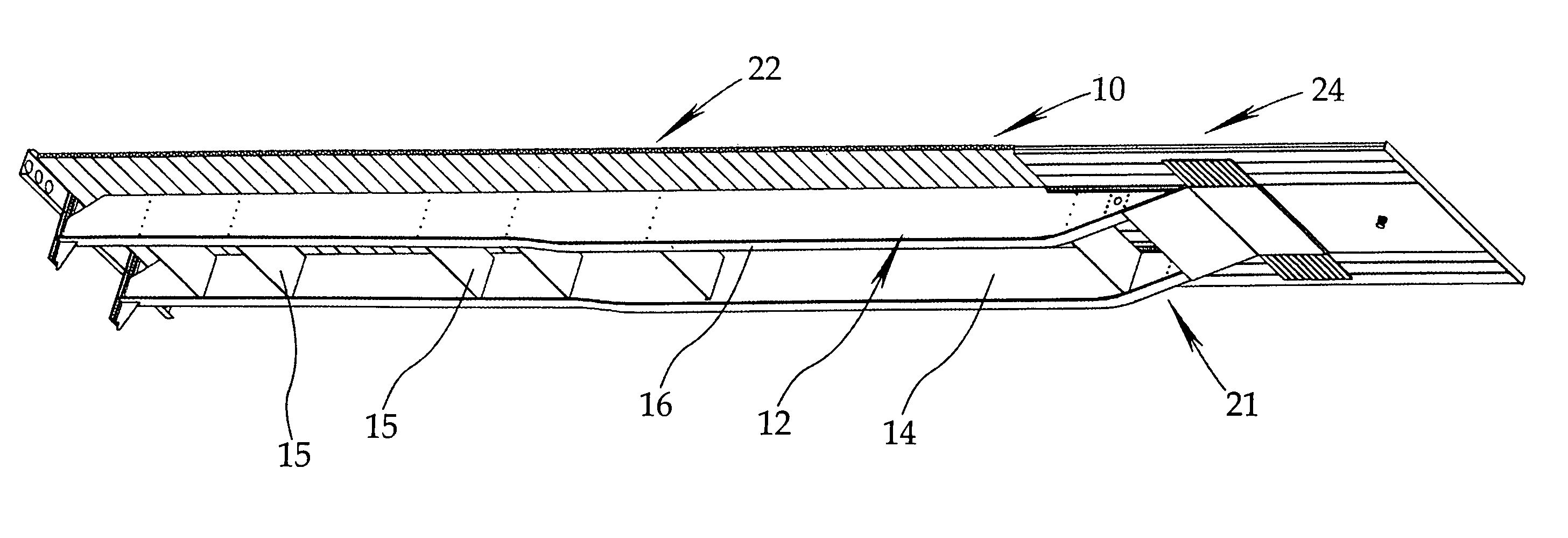
[0039]Referring to the drawings in greater detail and by reference characters thereto, there is illustrated in FIG. 1 a trailer body and which trailer body is generally designated by reference numeral 10. For purposes of clarity, the wheels and associated structure such as the axles are not shown. However, it will be understood that the trailer body would be mounted on a suitable structure.

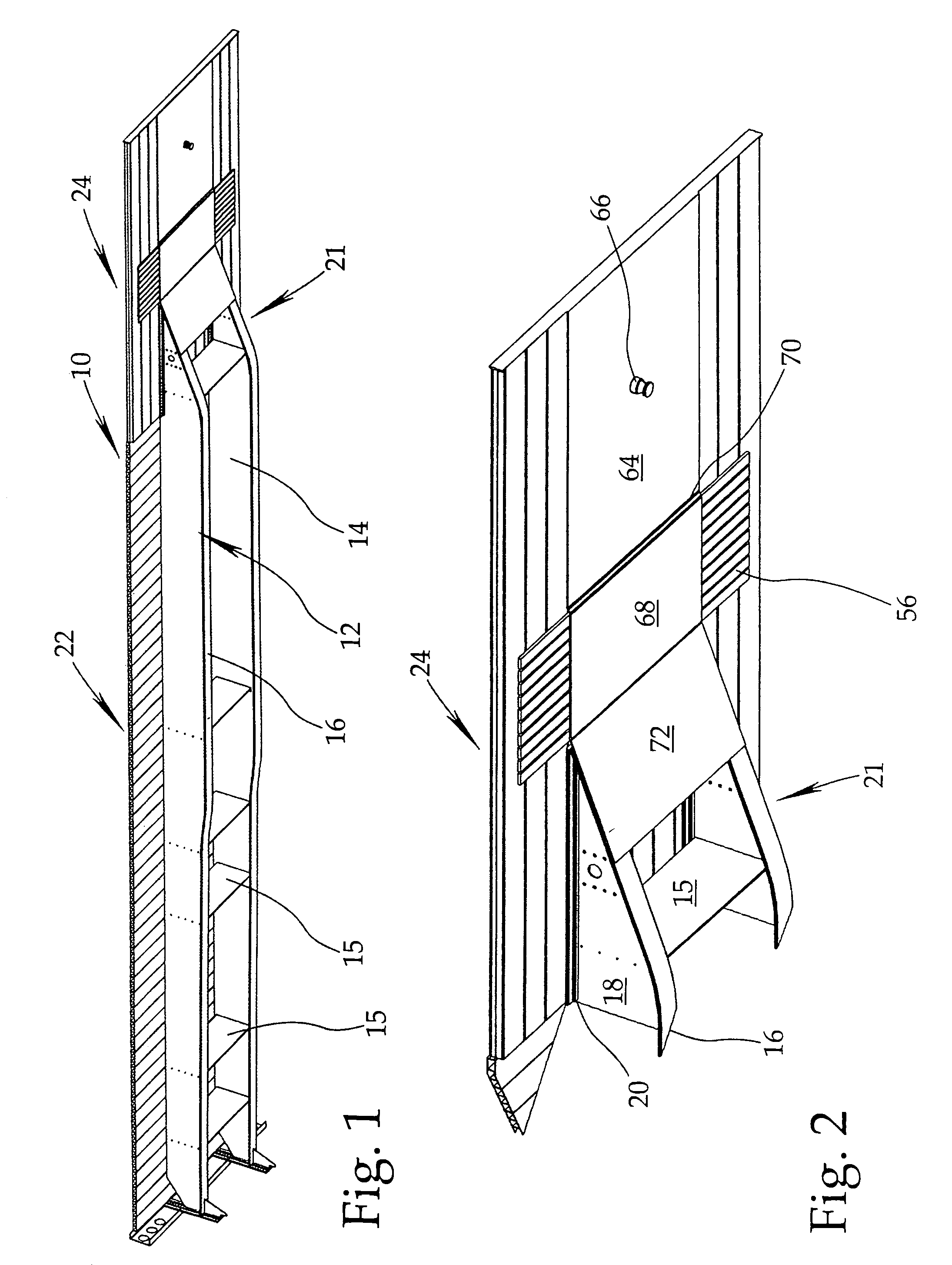
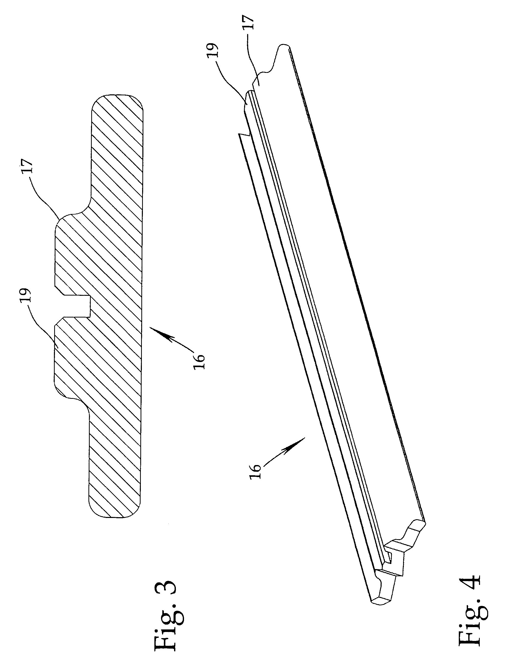
[0040]Trailer body 10 includes a pair of I beam structures 12 and 14 which are substantially identical and hence only I beam 12 will be described in detail herein. Transverse connecting members 15 extend between I beam structures 12 and 14. I beam structure 12 includes a bottom flange portion 16, a top flange portion 20, and a web 18 extending therebetween.

[0041]The bottom flange portion 16 is illustrated in FIG. 3 and as may be noted, has a pair of protrusions 17 and 19 which are designed to receive therebetween web 18.

[0042]As may be seen from FIG. 14, I beam structures 12 and 14 extend for subs...


PUM


Abstract

A floor for a trailer, the floor comprising a plurality of cells, each of the cells having a top plate, a bottom plate, and a plurality of parallel vertical members extending between the top plate and bottom plate, the cells being welded to adjacent cells and to longitudinally extending beams. The structure permits the trailer to be relatively low compared to other known designs and provides for a more stable trailer in use.

Description

FIELD OF THE INVENTION[0001]The present invention relates to vehicles and more particularly, relates to flat bed trailers.BACKGROUND OF THE INVENTION[0002]Flat bed trailers are trailers which, in many instances, lack rigid or permanent side walls. Such trailers are particularly useful for larger and irregularly shaped goods which do not require complete protection from the elements. The trailers are also useful in the small yards where the trailer may be loaded or unloaded on either side thereof. Some of the trailers may have temporary protection by means of side walls which are fabricated out of a canvas or a canvas like material.[0003]Generally, the trailers have a first load carrying portion which is at a lower height than a second load carrying portion which is located at the front (adjacent the cab) of the trailer. The raised portion is necessary to provide the structural integrity for the unit.[0004]Naturally, the raised portion lessens the amount of space available for storag...

Claims


Application Information

Patent Timeline
Patent Type & Authority Patents(United States)
IPC IPC(8): B62D25/20
CPCB62D25/2054B62D53/061
Inventor MESSIER, DONAT
Owner MESSIER DONAT
Why Eureka
Try Eureka