Lighting device and display device

a technology of lighting device and display device, which is applied in the direction of lighting and heating apparatus, planar/plate-like light guides, instruments, etc., can solve the problems of uneven luminance, difficult to improve both manufacturing facility and save manufacturing costs of lighting device, and achieve less luminance unevenness , the effect of reducing the amount of illumination light for image displaying

Inactive Publication Date: 2010-09-21
JVC KENWOOD CORP
View PDF11 Cites 23 Cited by
  • Summary
  • Abstract
  • Description
  • Claims
  • Application Information

AI Technical Summary

Benefits of technology

[0015]Even if producing white illumination light with less luminance unevenness with the use of a thick diffuser plate (or light guide plate) or the light mixing chamber, the illumination light is obtained due to transmission through a color filter for selecting only specific color (e.g. red, green or blue) component. In transmitting, as two-third components are absorbed by the color filter, the amount of illumination light for image displaying is reduced less than one-third of its original amount Due to such a loss of illumination light, greater number of light emitting elements are required to produce a display image having a required luminance. Therefore, it is difficult to improve both manufacturing facility and saving of manufacturing cost of the lighting device with reduction in the number of light emitting elements.
[0016]Under the above-mentioned problems, an object of the present invention is to provide a lighting device using red, green and blue light emitting elements as the light source, which device is capable of preventing loss of illumination light caused by a color filter, improving both manufacturing facility and saving of manufacturing cost of the lighting device with reduction in the number of light emitting elements while maintaining the required luminance, and also miniaturizing its own size.
[0017]Another object of the present invention is to provide a display device capable of effecting appropriate color reproduction originating in nonuse of color filters while providing a display image with high luminance, and also miniaturizing its own size.

Problems solved by technology

In the above-described lighting devices for the display device, if the light source is formed by a plurality of light emitting elements in line, then resultant illumination light emitted from the diffuser plate or the light guide plate is apt to cause luminance unevenness in proportion to an interval between the diffuser plate (or light guide plate) and the light emitting elements.
Particularly, the larger an interval between the adjoining light emitting elements gets, the more remarkable the luminance unevenness becomes.
For this reason, it is difficult to improve both manufacturing facility and saving of manufacturing cost of the lighting device with reduction in the number of light emitting elements due to the impossibility of broadening an interval between the adjoining light emitting elements.
Therefore, it is difficult to improve both manufacturing facility and saving of manufacturing cost of the lighting device with reduction in the number of light emitting elements.

Method used


Image

  • Lighting device and display device
  • Lighting device and display device
  • Lighting device and display device

Examples


second embodiment

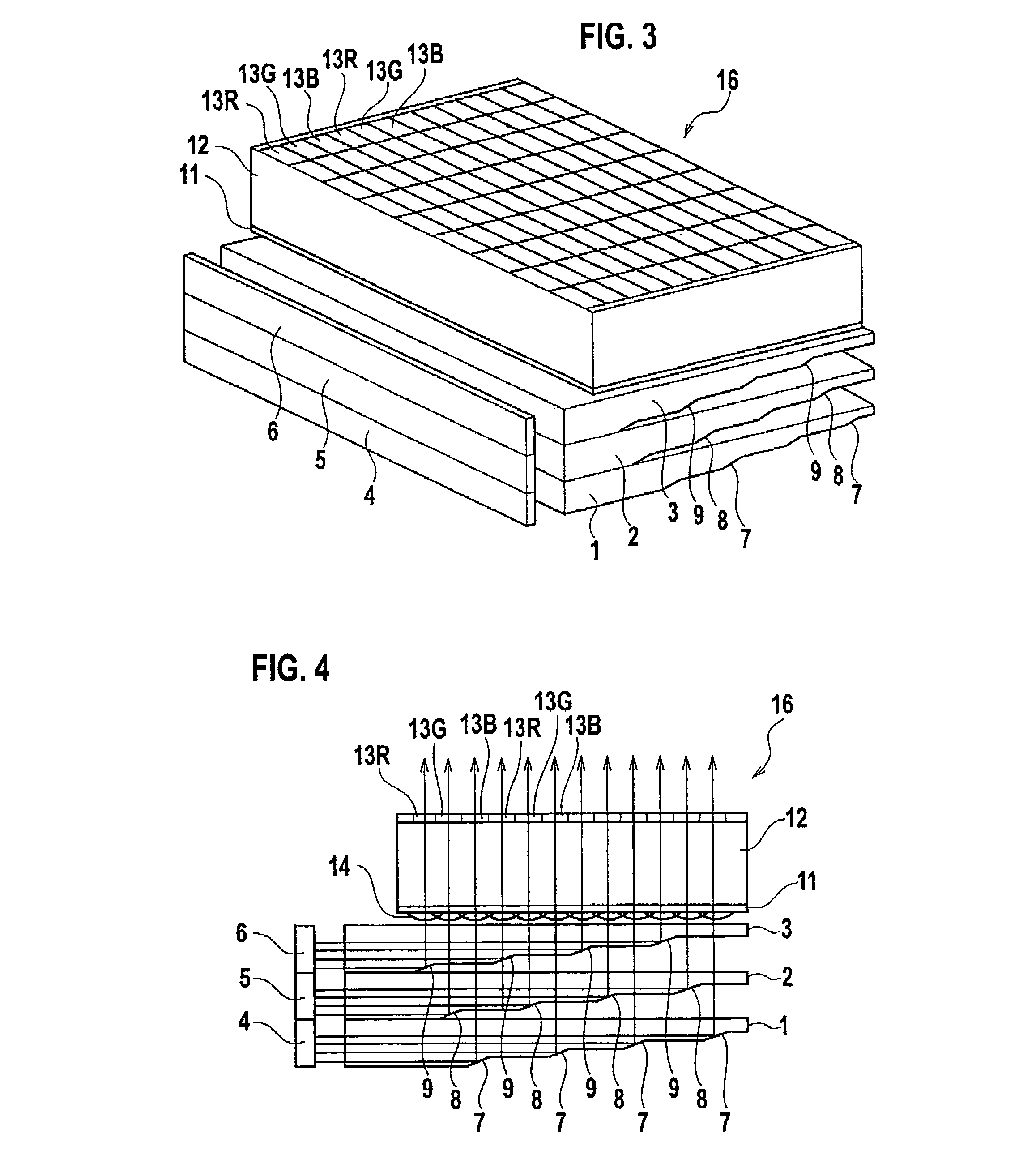
[0071]FIG. 8 is a side view showing the essential part of the lighting device in accordance with the present invention.

[0072]According to the second embodiment, as shown in FIG. 8, cylindrical lenses (or microlenses) 15 are formed on respective lateral surfaces of the light-transmitting guide plates 1, 2 and 3 on which the light fluxes from the light sources 4, 5 and 6 are incident. By the cylindrical lenses (or microlenses) 15, the light fluxes from the light sources 4, 5 and 6 can be modified to high-accuracy parallel fluxes in the light-transmitting guide plates 1, 2 and 3, improving the light utilization efficiency of the light fluxes from the light sources 4, 5 and 6. In addition, the intensity distribution of the light fluxes emitted from the lighting device in front side is uniformed to allow the emitted light to be reduced in luminance unevenness.

[0073]Desirably, the cylindrical lenses (or microlenses) 15 are formed by aspherical cylindrical lenses (or microlenses) optimized...

third embodiment

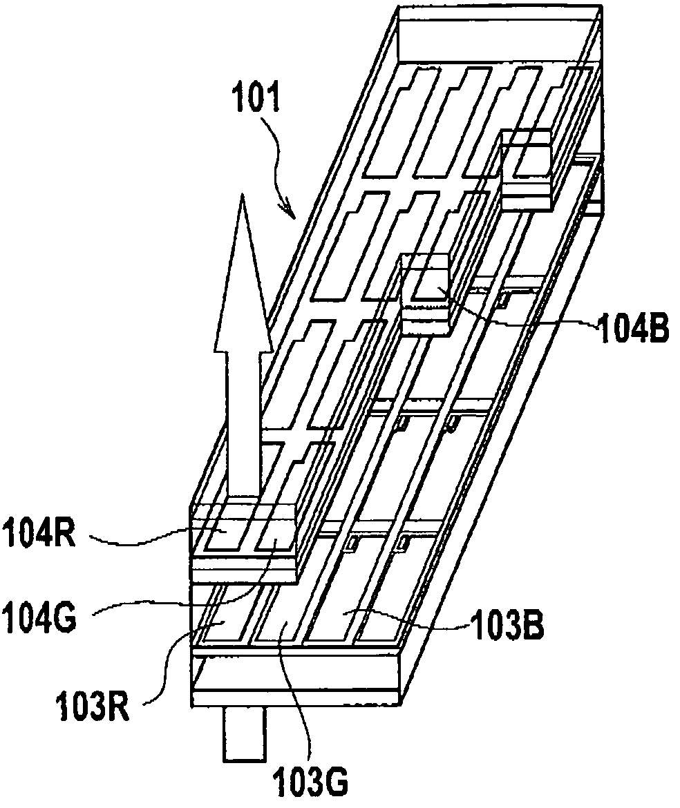
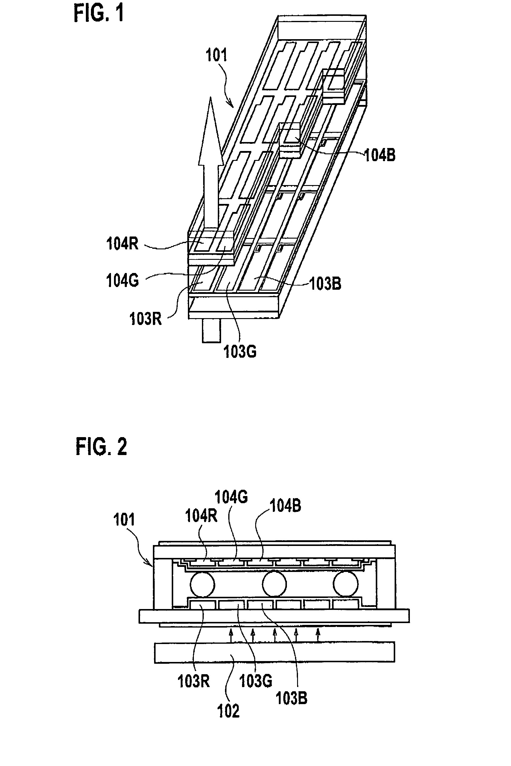
[0081]FIG. 9 is a perspective view showing the constitution of the lighting device and the display device in accordance with the present invention.

[0082]As shown in FIG. 9, the lighting device of the present invention includes a plurality of (at least three) rod-shaped light-transmitting guide bodies arranged in parallel with each other. In this embodiment, the lighting device includes first, second and third light-transmitting guide bodies 201, 202 and 203 juxtaposed to each other. In arrangement, the second light-transmitting guide body 202 is arranged on one lateral side of the first light-transmitting guide body 201, while the third light-transmitting guide body 203 is arranged on one lateral side of the second light-transmitting guide body 202.

[0083]The first to third light-transmitting guide bodies 201, 202 and 203 are rod-shaped to have rectangular cross sections and made of transparent material. These light-transmitting guide bodies 201, 202 and 203 are arranged in parallel ...

fourth embodiment

[0115]FIG. 14 is a side view showing the essential part of the lighting device in accordance with the present invention.

[0116]According to the fourth embodiment, as shown in FIG. 14, convex lenses 215 are formed on respective one ends of the light-transmitting guide bodies 201, 202 and 203 on which the light fluxes from the light sources 204, 205 and 206 are incident. By the convex lenses 215, the light fluxes from the light sources 204, 205 and 206 can be modified to high-accuracy parallel fluxes in the light-transmitting guide bodies 201, 202 and 203, improving the light utilization efficiency of the light fluxes from the light sources 204, 205 and 206. In addition, the intensity distribution of the light fluxes emitted from the light-transmitting guide plates 217 in front is uniformed to allow the emitted light to be reduced in luminance unevenness.

[0117]Desirably, the convex lenses 215 are formed by aspherical cylindrical lenses optimized in accordance with emission distribution...


PUM


Abstract

A lighting device includes a plurality of light-transmitting guide plates 1, 2, 3 laminated in at least three layers and a plurality of light emitting elements 4, 5, 6 arranged so as to oppose to respective lateral sides of the light-transmitting guide plates 1, 2, 3 to allow luminance flux in different color with respect to each light-transmitting guide plate to be incident on the corresponding light-transmitting guide plate. Each of the light-transmitting guide plates 1, 2, 3 has a plurality of reflecting surfaces 7, 8, 9 formed on the backside of the plate to change a propagation direction of the luminance flux propagated in the each light-transmitting guide plate, allowing the luminance flux, of which propagation direction has been changed by the reflecting surfaces 7, 8, 9, to be emitted from the front side of the each light-transmitting guide plates.

Description

BACKGROUND OF THE INVENTION[0001]1. Field of the Invention[0002]The present invention relates to a lighting device having a surface light source device and a light guide plate, and a display device having the lighting device. More particularly, the invention relates to a lighting device using a number of point light sources such as LED (light emitting diode), and a display device having the lighting device as a surface light source device.[0003]2. Description of Related Art[0004]There has been proposed a display device configured to display an image by illuminating a spatial light modulating element, such as LCD (liquid crystal display), using a lighting device.[0005]FIG. 1 is a perspective view showing the constitution of a display device using a conventional transmission TFT-LCD (thin film transistor-liquid crystal display)[0006]FIG. 2 is a sectional view of the display device of FIG. 1.[0007]In the display device using a non-illuminant spatial light modulating element represented...

Claims


Application Information

Patent Timeline
Patent Type & Authority Patents(United States)
IPC IPC(8): F21V7/04
CPCG02B6/002G02B6/0028G02B6/0048G02B6/0076G02B6/0055G02B6/0068G02F2001/133622G02F1/133622
Inventor SEGAWA, MASARU
Owner JVC KENWOOD CORP
Why Eureka
Try Eureka