Flux concentrator for biomagnetic particle transfer device

a biomagnetic particle and flux concentrator technology, applied in the field of analytical separation and combining samples, can solve the problems of difficult manufacturing and expensive, thin-walled tips are difficult to handle, and are not particularly durable to withstand rinsing

Inactive Publication Date: 2010-09-21
FESTO CORPORATION
View PDF29 Cites 38 Cited by
  • Summary
  • Abstract
  • Description
  • Claims
  • Application Information

AI Technical Summary

Benefits of technology

[0018]In a preferred embodiment, a transfer device is provided which includes an array of pins and a magnet actuator system for selectively applying and removing the magnetic force at the end of at least one pin of the pin array. In this embodiment, the magnetizable tip of the present invention is also provided in an array matching in number and spacing as that of the pins. The tips can thus be removed from the pins as a single unit.

Problems solved by technology

One drawback resides in the fact that the ends of the magnetic rods or pins must come into direct contact with the magnetic particles in the liquid sample to ensure a sufficiently strong magnetic field to collect the particles.
Such thin-walled tips are difficult to manufacture and are expensive.
Such thin-walled tips are difficult to handle and are not particularly durable to withstand rinsing and sterilization.

Method used


Image

  • Flux concentrator for biomagnetic particle transfer device
  • Flux concentrator for biomagnetic particle transfer device
  • Flux concentrator for biomagnetic particle transfer device

Examples


example

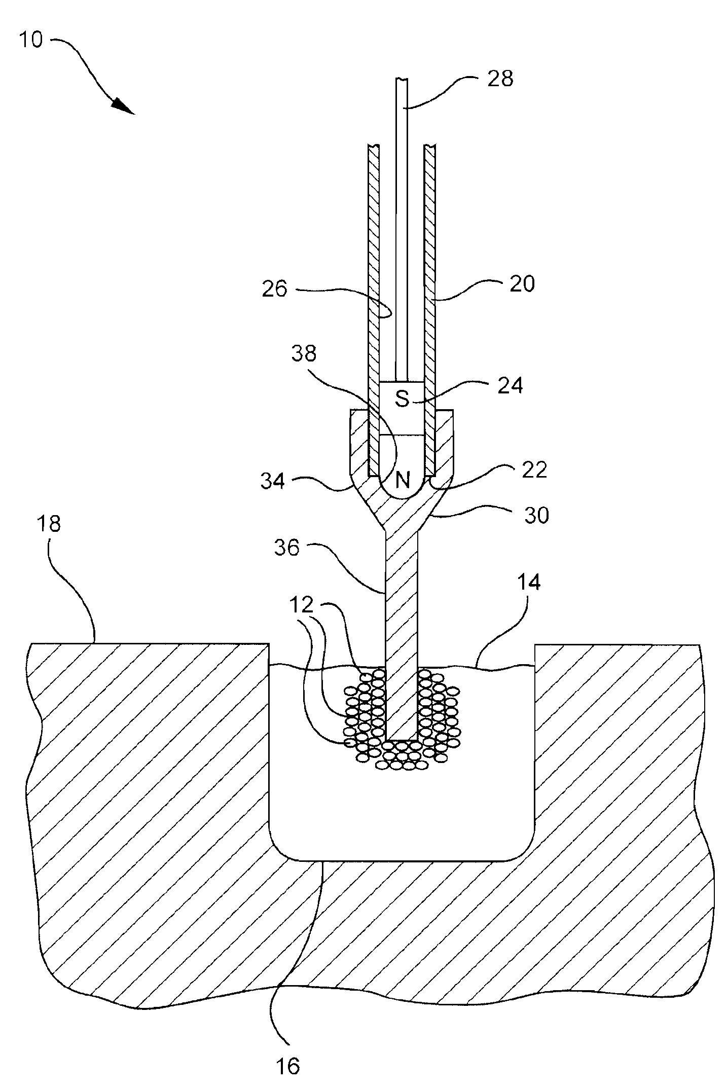
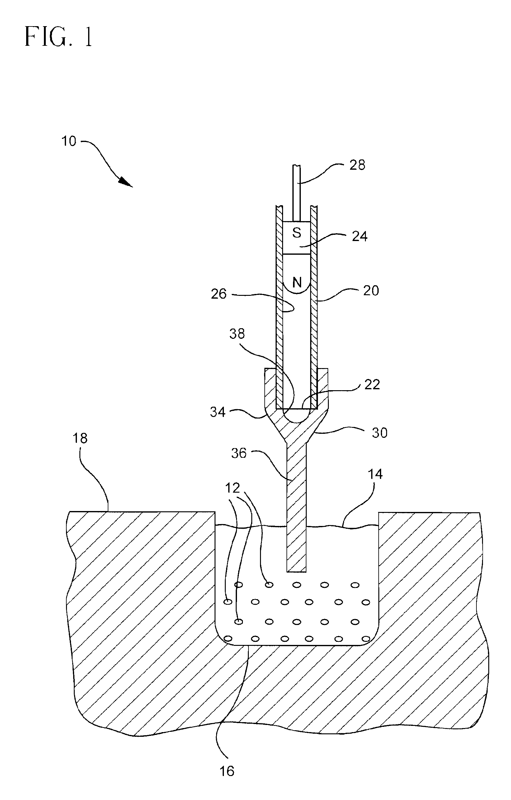
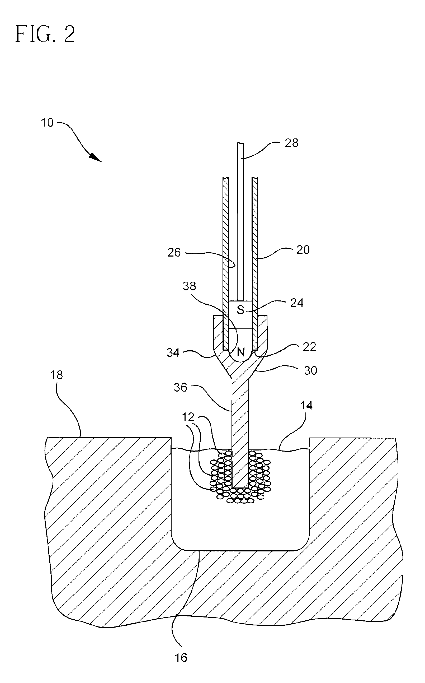
[0046]An analysis was conducted for a Ø3 mm×21 mm NdFeB, grade N-45 permanent magnet 24 slidably received in a tubular pin 20. FIG. 8 shows the magnetic force to gravity ratio applied by a transfer device 10 without a magnetizable tip 30 according to the present invention attached thereto. As shown in FIG. 8, without bringing the lower tip of this permanent magnet 24 below the level of the fluid 14 contained within the microplate well 16, the biomagnetic particles 12 held in suspension to a depth of ˜7 mm (14 mm-deep wells) would be subjected to a magnetic force twice that of gravity.

[0047]Adding a tapered-cylinder flux concentrator tip 30, according to the present invention, to the magnet 24 resulted in the vertical and horizontal G-force-component magnitude plots shown in FIGS. 9 and 10. These simulations indicate that the Ø3 mm×21 mm permanent magnet 24 would successfully collect biomagnetic particles using the collection rod.

[0048]The magnet alone (FIG. 8) has an upward force ex...


PUM

PropertyMeasurementUnit
depthaaaaaaaaaa
depthaaaaaaaaaa
depthaaaaaaaaaa

Abstract

A tip for a biomagnetic particle transfer device generally includes a solid body made from a highly magnetically permeable material and having a shape adapted to concentrate a magnetic field generated by the transfer device on the body. The tip body preferably includes a truncated cone-shaped portion and a solid probe portion. The cone-shaped portion defines an attachment end engageable with an end of the transfer device and an apex opposite the attachment end. The probe portion extends from the apex of the cone-shaped portion, and the magnetic field is concentrated on the probe portion.

Description

CROSS-REFERENCE TO RELATED APPLICATIONS[0001]This application claims the benefit of U.S. Provisional Application No. 60 / 880,681, filed on Jan. 16, 2007, which is incorporated by reference herein in its entirety for all purposes.BACKGROUND OF THE INVENTION[0002]The present invention relates generally to the field of analytical separation and combining of samples and, more particularly, to a temporarily magnetizable biomagnetic particle collection, extraction and transfer device and a magnetic flux concentrator therefor.[0003]Analytic and diagnostic procedures in the laboratory often require the transfer of a plurality of samples, simultaneously, from one array of liquid-containing wells to another. In order to transfer, add, collect or combine liquids, various multi-transferring systems have been devised. The most commonly used is a multi-pipette which collects liquid from an array of source wells for transfer to an array of target wells by application or release of application, resp...

Claims


Application Information

Patent Timeline
Patent Type & Authority Patents(United States)
IPC IPC(8): B03C1/02
CPCB03C1/286Y10T436/25375
Inventor COOK, DOUGLAS LEEBRAY, THOMAS E.
Owner FESTO CORPORATION
Why Eureka
Try Eureka