Electronic device using movement of particles

Active Publication Date: 2010-03-04
KONINKLIJKE PHILIPS ELECTRONICS NV
View PDF6 Cites 2 Cited by
  • Summary
  • Abstract
  • Description
  • Claims
  • Application Information

AI Technical Summary

Benefits of technology

[0028]In all cases the particle quantity defines an element state, for example for display applications, this method provides repeatable and accurately controllable grey levels. In particular, the drive method can be considered to suppress the impact of EHDF by interrupting the flow.
[0029]For an arrangement with a gate electrode, when the first voltage of the pulse waveform is applied, the gate electrode can prevent movement of particles from the output electrode to the reset electrode, so that particles already at the output electrode are held there. When t

Problems solved by technology

It has been observed by the inventors that EHDF is often unstable, random and non-linear in nature, thereby causing the particle trajectories to deviate substantially from the intended particles trajectory.
It may therefore be understood that the heavily disturbed particle trajectories lead to irreproducibili

Method used


Image

  • Electronic device using movement of particles
  • Electronic device using movement of particles
  • Electronic device using movement of particles

Examples


first embodiment

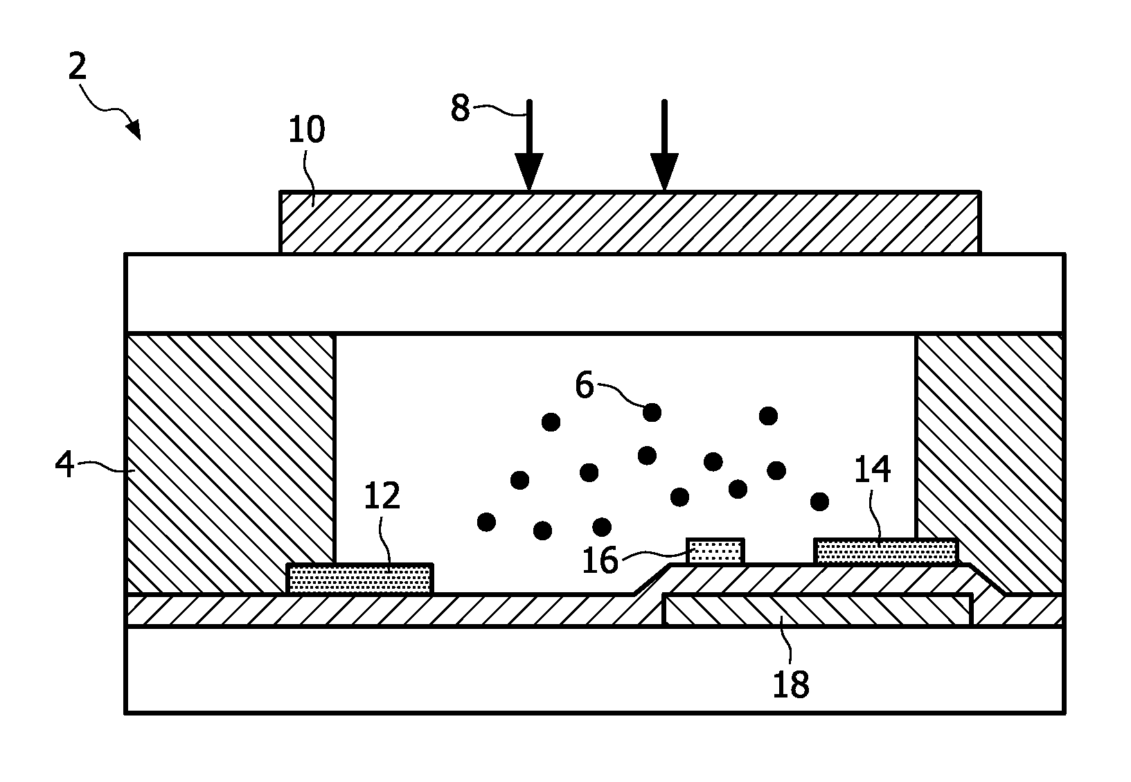
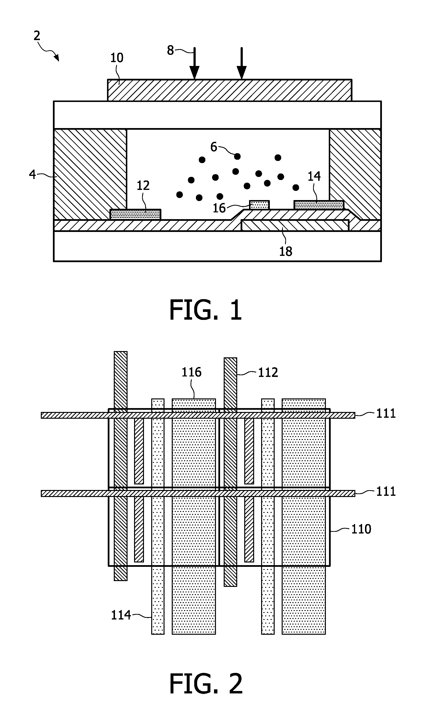
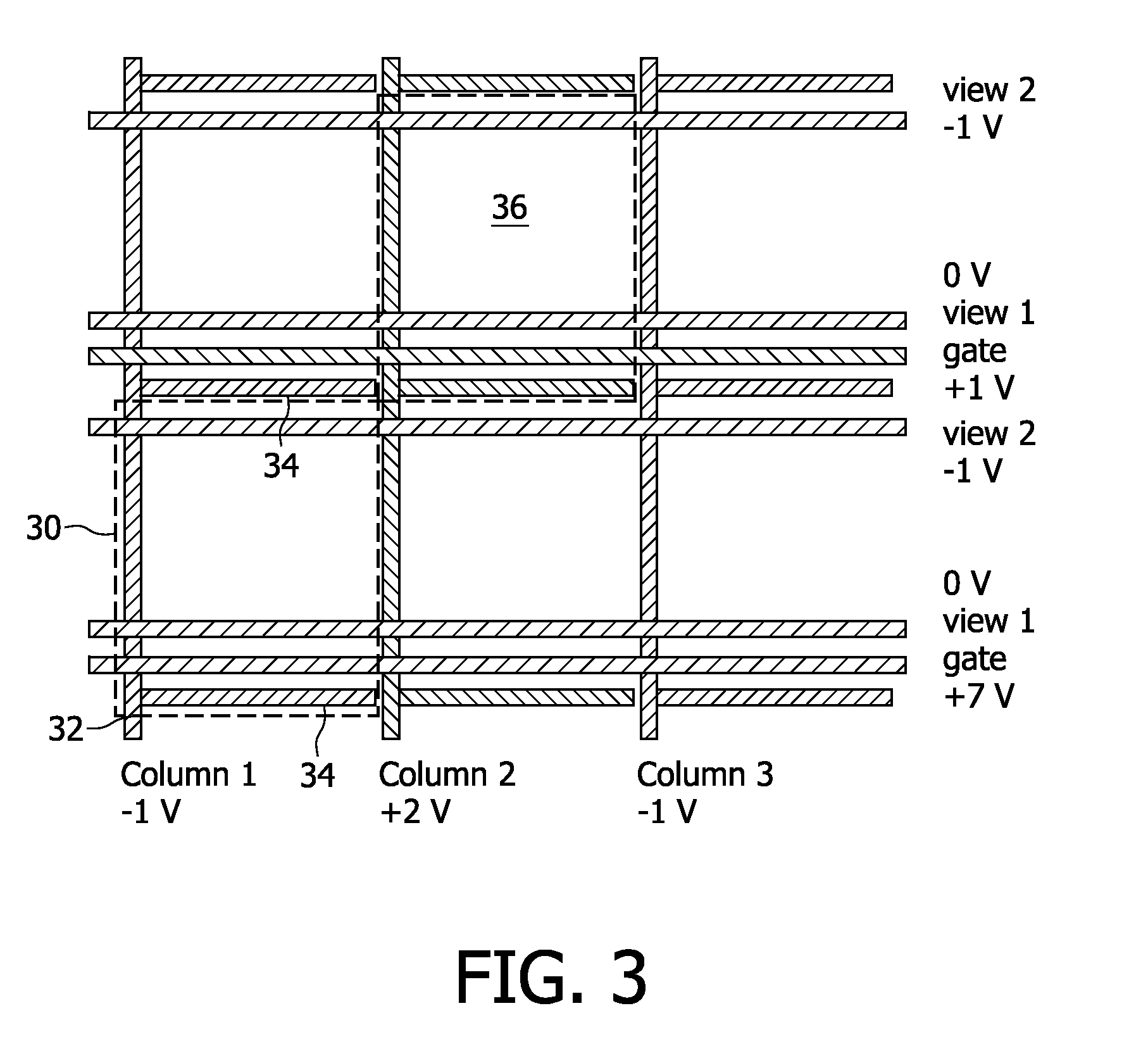
[0077]In the invention, rather than applying a stationary potential to the collector electrodes for a select-write pixel or row, the potential at the collector (column) of the select-write pixel or row is modulated with a repetitive cycle as shown in FIG. 5 between a pixel-write and a pixel non-write state.

[0078]FIG. 5 shows the pixel writing phase having time duration t, and this is the time during which there is particle movement to the temporary storage electrode, namely the particle movement shown in the select-write part of FIG. 4. This time period t comprises a series of N pulses on the collector electrode between the write and non-write voltages, namely +10 V and −10 V taking the example voltages in FIG. 4, or +2 V and −1 V taking the example voltages in FIG. 3. For each pulse 50, the duty cycle determines the grey level. This duty cycle corresponds to the duty cycle for the full period of time (t) and determines the grey-level. Thus, different grey-levels (for example 255 fo...

second embodiment

[0091]In a second embodiment, instead of resetting the pigments to the collector electrode, the pigments can be reset to the first display electrode (view1), namely the display electrode nearest to the gate electrode. Pigments can then be extracted in small and controlled packets towards the collector electrode by using the modulation scheme described above applied to either the collector, or the view1 electrode.

[0092]In the latter case, for the non-write pixels the collector potential is repelling, whilst for the pixel-select pixel-write case the collector potential is attracting. Thus after removal of the desired amount of pigment, the display common evolution phase again follows as described above.

[0093]In a third embodiment, rather than having a constant addressing period per pixel and a variable duty-cycle, a fixed duty-cycle can be applied for a variable amount of time whilst applying different potentials, or signs, to the collector electrodes, thereby again resulting in well ...

fourth embodiment

[0094]In a fourth embodiment, both the duty-cycle and the addressing time per pixel are variable, and different combinations of drive scheme can be applied at different times.


PUM


Abstract

A method is provided of driving an electronic device comprising an array of device elements, each device element comprising particles which are moved to control a device element state, and each device element comprising a collector electrode, and an output electrode. The method comprises: in a reset phase, applying a first set of control signals to control the device to move the particles to the a reset electrode; and in an addressing phase, applying a second set of control signals to control the device to move the particles from the reset electrode such that a desired number of particles are at the output electrode. The second set of control signals comprises a pulse waveform oscillating between first and second voltages in which the first voltage is for attracting the particles to the reset electrode and the second voltage is for attracting the particles from the reset electrode to the output electrode, and wherein the duty cycle of the pulse waveform determines the proportion of particles transferred to the output electrode in the addressing phase. This control method provides well-controlled packets of particles which are collected in a vortex at the reset electrode before being passed on, in part, towards the output electrode (for example via the gate electrode).

Description

FIELD OF THE INVENTION[0001]This invention relates to an electronic device using movement of particles. One example of this type of device is an electrophoretic display.BACKGROUND OF THE INVENTION[0002]Electrophoretic display devices are one example of bistable display technology, which use the movement of charged particles within an electric field to provide a selective light scattering or absorption function.[0003]In one example, white particles are suspended in an absorptive liquid, and the electric field can be used to bring the particles to the surface of the device. In this position, they may perform a light scattering function, so that the display appears white. Movement away from the top surface enables the color of the liquid to be seen, for example black. In another example, there may be two types of particle, for example black negatively charged particles and white positively charged particles, suspended in a transparent fluid. There are a number of different possible con...

Claims


Application Information

Patent Timeline
IPC IPC(8): G09G5/00
CPCG09G3/2018G09G3/2081G09G2320/0233G09G2300/0434G09G2310/06G09G3/3446
Inventor VAN DELDEN, MATINUS HERMANUS WILHELMUS MARIABUDZELAAR, FRANCISCUS PAULUS MARIAROOSENDAAL, SANDER JURGEN
Owner KONINKLIJKE PHILIPS ELECTRONICS NV
Why Eureka
Try Eureka