Adaptive modulation scheme and data rate control method

a modulation scheme and data rate technology, applied in the field of radio communication systems, can solve problems such as data location deviation, continuous errors, and suppression of the throughput of data signals

Inactive Publication Date: 2010-09-21
HITACHI LTD
View PDF7 Cites 4 Cited by
  • Summary
  • Abstract
  • Description
  • Claims
  • Application Information

AI Technical Summary

Benefits of technology

[0010]The present invention has been conceived and developed to solve the problems described above. In the case where the modulation type is controlled for each subcarrier in the OFDM, for example, communication can be realized even if the modulation type is not always matched precisely between the transmitter station and receiver station. Therefore, an object of the present invention is to provide a radio communication system in which the modulation type can be switched for each subcarrier, while the number of control signals for controlling the modulation type is reduced, and the throughput of the communication as a whole can be controlled according to the total quality of the propagation path.

Problems solved by technology

If the transmitter station and the receiver station have a different modulation type, the data location is deviated and continuous errors occur.
Therefore, when it is attempted to control the modulation type for each subcarrier in the OFDM system, a problem arises, in that the throughput of the data signal itself is suppressed because the signals for controlling the modulation type, such as the modulation type, indicating signal and the training signal, increase.
On the contrary, when the number of signals for controlling the modulation type, such as the modulation type indicating signal and the training signal, is reduced so as to not suppress the throughput of the data signal, a problem also arises in that the degree of freedom in the modulation type control is reduced, fine control becomes impossible, and communication by fully utilizing the propagation path cannot be realized.

Method used


Image

  • Adaptive modulation scheme and data rate control method
  • Adaptive modulation scheme and data rate control method
  • Adaptive modulation scheme and data rate control method

Examples


Embodiment Construction

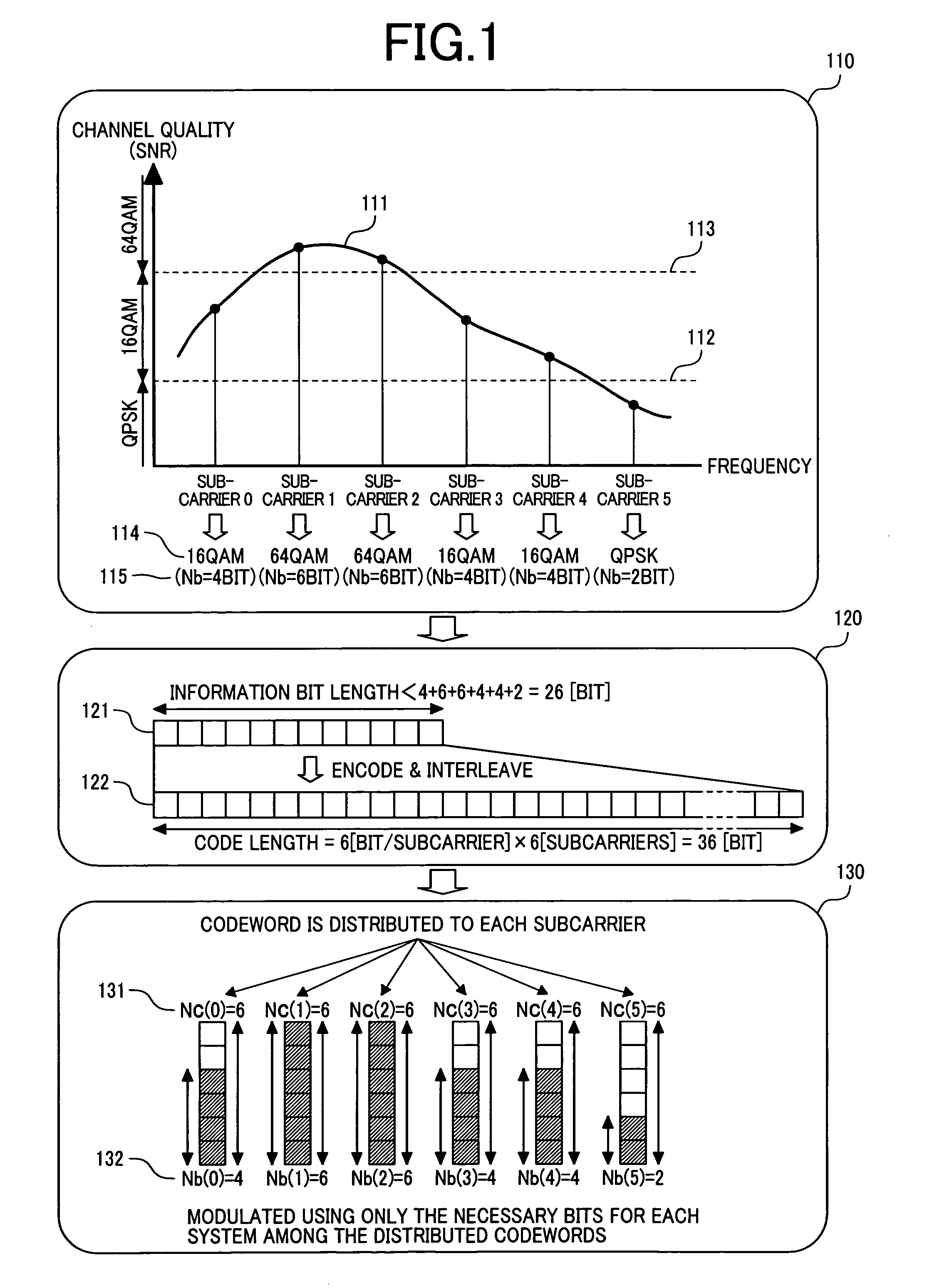
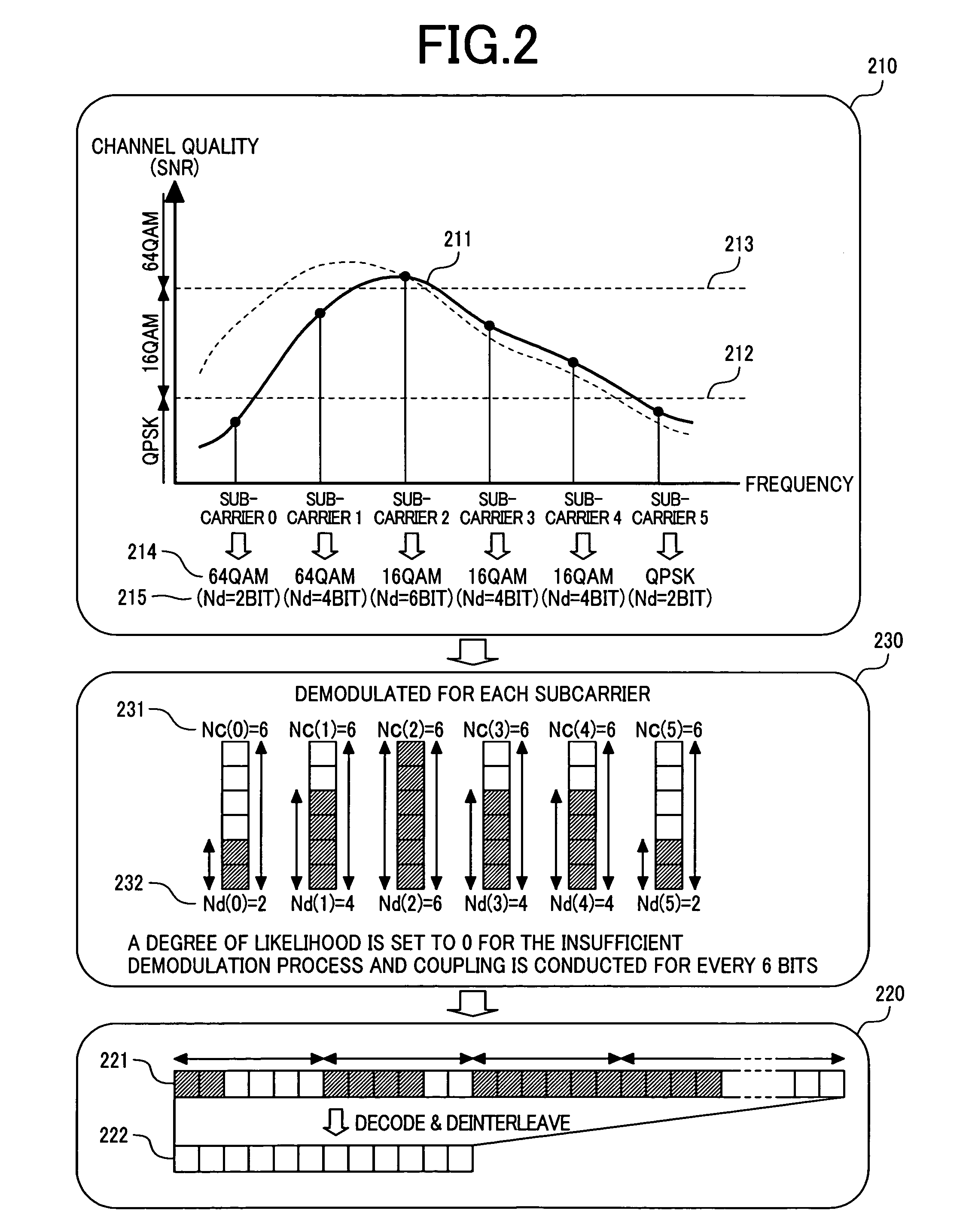
[0029]Preferred embodiments of the present invention will be described with reference to the accompanying drawings. However, as an example, the maximum number of bits per symbol of each subcarrier is set to 6 bits and as a modulation type, an adaptive modulation type using 64 QAM or 16 QAM or QPSK has been used. However, it should be understood that the present invention is not limited to such maximum bits and modulation type. Namely, the present invention can be adapted in general to a system in which the maximum bits per symbol is set to 2m bits and demodulation is conducted with the 22kQAM (k is a natural number equal to or less than m) modulation type. Moreover, the 4QAM modulation type, in which k=1, indicates a modulation type similar to QPSK.

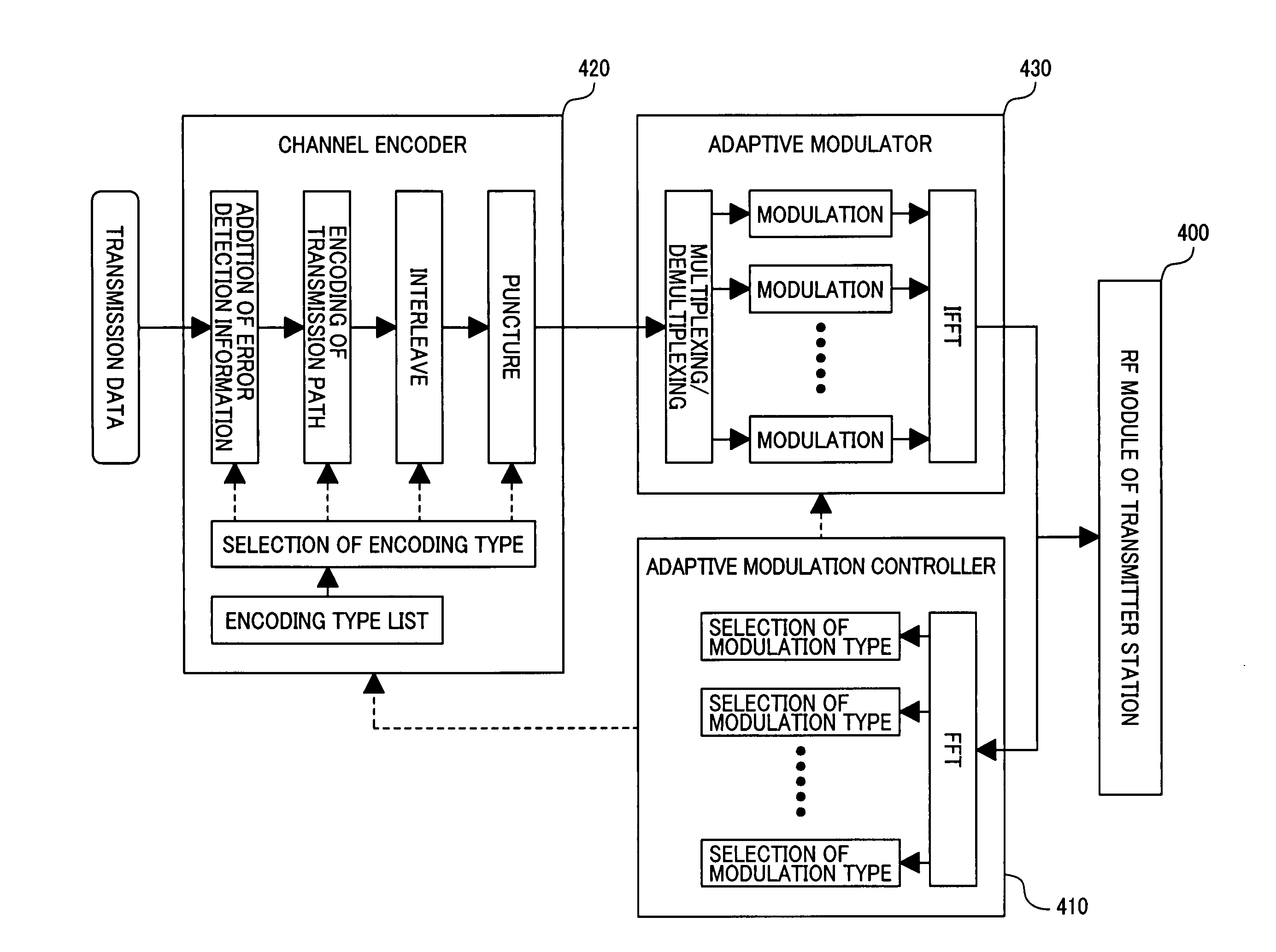
[0030]First, an example of the configuration of the transmitter station and the receiver station and the flow of signals will be described on the basis of the structural diagrams of the transmitter station and receiver station, using the ...


PUM


Abstract

A transmitter station and receiver station have common maximum number of transmission bits per symbol of each subcarrier and information of encoding types to be selected. The transmitter station selects the modulation type from the propagation path quality of each subcarrier, executes encoding with the encoding type corresponding to the number of bits for communication with the selected modulation type, distributes the maximum number of transmission bits per symbol of each subcarrier by dividing the code, and transmits the data through modulation of only the number of bits for communication with the selected modulation type among distributed bits in each subcarrier. The receiver station executes demodulation by selecting the modulation type used for demodulation from the propagation path quality, summarizes the demodulation result with addition of reception of the signal having a zero degree of likeliness for the number of wanted bits, and executes decoding to the result of demodulation.

Description

CLAIM OF PRIORITY[0001]The present application claims priority from Japanese application JP 2004-061578, filed on Mar. 5, 2004, the content of which is hereby incorporated by reference into this application.FIELD OF THE INVENTION[0002]The present invention relates in general, to a radio communication system; and, more particularly, the invention relates to a modulation type and data rate control method which can adapt to variations in the quality in each propagation path in a radio communication system using multiple propagation paths, such as provided in a multi-carrier radio communication system.BACKGROUND OF THE INVENTION[0003]In view of the increasing data rate per time in the conventional radio communication system, a multi-level modulation technique for propagating information of multiple bits per symbol has been developed. In such a multi-level modulation technique, the maximum throughput increases, when the quality of the propagation paths is further improved, as the number ...

Claims


Application Information

Patent Timeline
Patent Type & Authority Patents(United States)
IPC IPC(8): H04B7/02H04B1/00H04B7/26H04J11/00H04L27/36H04L27/38
CPCH04L1/0003H04L1/0009H04L1/0021H04L5/0046H04L27/0008H04L5/006
Inventor TAMAKI, SATOSHIYANO, TAKASHISAITO, TOSHIYUKIHANAOKA, SEISHI
Owner HITACHI LTD
Why Eureka
Try Eureka