
Field emitter based electron source with minimized beam emittance growth

a field-emitter and electron beam technology, applied in the field of field-emitter electron emitters, can solve the problems of increasing the degradation of negative impact on the quality of the electron beam, etc., and achieves the effects of minimal emittance growth in the electron beam, low voltage extraction, and minimal degradation of the electron beam

Inactive Publication Date: 2010-09-21
GENERAL ELECTRIC CO
View PDF12 Cites 130 Cited by
  • Summary
  • Abstract
  • Description
  • Claims
  • Application Information

AI Technical Summary

Benefits of technology

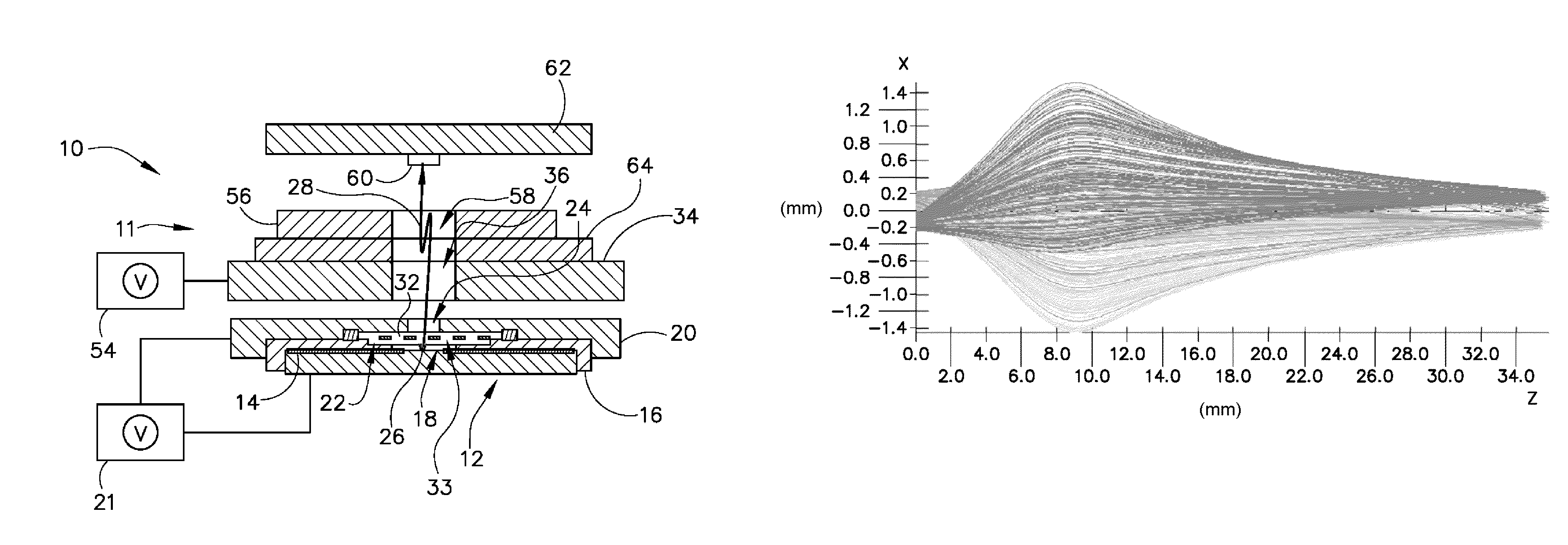
"The invention provides a field emitter unit that minimizes degradation of the electron beam and allows for focusing of the electron beam into a desired spot size. This is achieved through an emittance compensation electrode that functions to control emittance growth of the electron beam. The invention also includes a meshed grid and an emittance compensation electrode to enhance intensity and uniformity of an electric field at a surface of the emitter element. Additionally, the invention provides a cathode assembly and a multiple spot x-ray source that include a plurality of field emitter units with a meshed grid and an emittance compensation electrode to control electron beam emittance growth and form a focal spot on the target anode. These technical effects improve the performance and reliability of field emitter units in various applications such as electron guns and x-ray sources."

Problems solved by technology

However, while the grid mesh significantly improves the extraction efficiency, it also has a negative impact on electron beam quality due to the interaction of the electron beam with the grid.
That is, interaction of the electron beam with the grid can increase the degradation of the electron beam quality by increasing beam emittance, which prevents the electron beam from focusing onto a small, useable focal spot on the anode.

Method used


Image

  • Field emitter based electron source with minimized beam emittance growth
  • Field emitter based electron source with minimized beam emittance growth
  • Field emitter based electron source with minimized beam emittance growth

Examples


Embodiment Construction

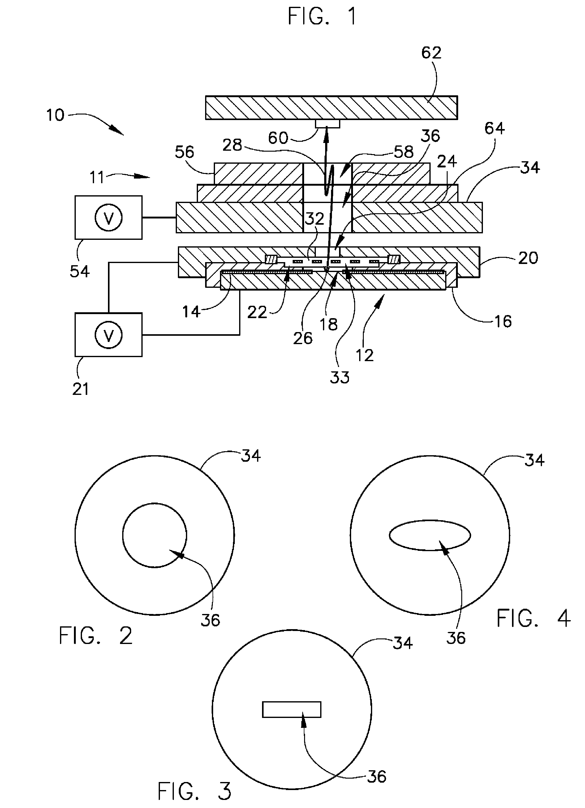
[0024]The operating environment of embodiments of the invention is described with respect to an electron gun and x-ray source that includes a field emitter based cathode. That is, the electron beam emission and electron beam compression schemes of the invention are described as being provided for an electron gun and field emitter based x-ray source. However, it will be appreciated by those skilled in the art that embodiments of the invention for such electron beam emission and electron beam compression schemes are equally applicable for use with other cathode technologies, such as dispenser cathodes and other thermionic cathodes. The invention will be described with respect to a field emitter unit, but is equally applicable with other cold cathode and / or thermionic cathode structures.

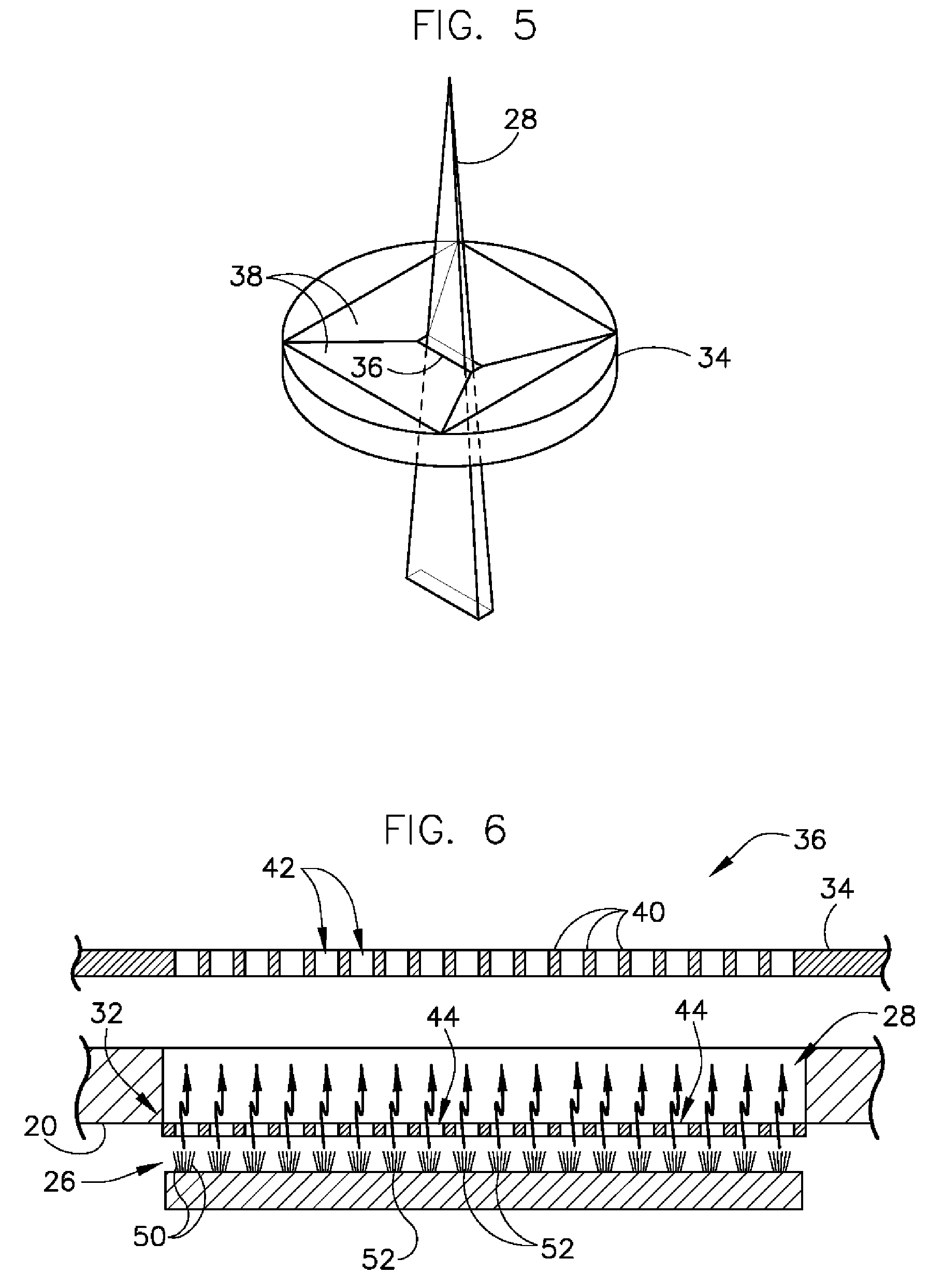
[0025]Referring to FIG. 1, a cross-sectional view of a single electron generator 10 (i.e., electron gun) is depicted according to one embodiment of the invention. As will be explained in greater detail ...


PUM


Abstract

A system and method for limiting emittance growth in an electron beam is disclosed. The system includes an emitter element configured to generate an electron beam and an extraction electrode positioned adjacent to the emitter element to extract the electron beam out therefrom, the extraction electrode including an opening therethrough. The system also includes a meshed grid disposed in the opening of the extraction electrode to enhance intensity and uniformity of an electric field at a surface of the emitter element and an emittance compensation electrode (ECE) positioned adjacent to the meshed grid on the side of the meshed grid opposite that of the emitter element and configured to control emittance growth of the electron beam.

Description

BACKGROUND OF THE INVENTION[0001]The present invention relates generally to field-type electron emitters, and, more particularly, to a system for limiting emittance growth in an electron beam. A field emitter unit includes an emittance compensation electrode that functions to minimize degradation of the electron beam and allow for focusing of the electron beam into a desired spot size.[0002]Electron emissions in field-type electron emitter arrays are produced according to the Fowler-Nordheim theory relating the field emission current density of a metal surface to the electric field at the surface. Most field-type electron emitter arrays generally include an array of many field emitter devices. Emitter arrays can be micro- or nano-fabricated to contain tens of thousands of emitter devices on a single chip. Each emitter device, when properly driven, can emit a beam or current of electrons from the tip portion of the emitter device. Field emitter arrays have many applications, one of w...

Claims


Application Information

Patent Timeline
Patent Type & Authority Patents(United States)
IPC IPC(8): G21G4/00H01J35/14H01J35/02H01J35/00
CPCH01J35/065H01J2235/062
Inventor ZOU, YUNCAO, YANGINZINNA, LOUIS PAULNECULAES, VASILE BOGDAN
Owner GENERAL ELECTRIC CO
Learn More