Field emitter based electron source for multiple spot x-ray

Active Publication Date: 2009-07-23
GENERAL ELECTRIC CO
View PDF20 Cites 60 Cited by
  • Summary
  • Abstract
  • Description
  • Claims
  • Application Information

AI Technical Summary

Benefits of technology

[0011]According to another aspect of the invention, an x-ray tube includes a housing enclosing a vacuum-sealed chamber therein and a target generally located at a first end of the chamber and configured to produce an array of x-ray focal spots providing tomographic imaging of an object when impinged by a plurality of electron beams. The multiple spot x-ray generator also includes a target shield housing the target and configured to trap ions therein generated by the interaction of the plurality of electron beams and the target and to intercept backscattered electrons, and a field emitter array generally located at a second end of the chamber to generate the plurality of electron beams and transmit the plurality of electron beams toward the target, the

Problems solved by technology

At present, field emitter arrays are not known to be robust enough for use in several potential commercial applications, such as for use in x-ray tubes.
Many existing emitter array designs are susceptible to operational failures and structural wear from electrical arcing.
When one emitter of an emitter array experiences arcing in either form, or “breaks down,” the insulating layer will no longer be able to support a voltage or electrical bias sufficient for electron emission to continue at the other emitters of the array.
In addition, high temperatures produced by the short circuit current can cause wear or damage to the emitter as well as neighboring emitters.
When used as an electron source in an x-ray tube application, field emitter arrays create additional

Method used


Image

  • Field emitter based electron source for multiple spot x-ray
  • Field emitter based electron source for multiple spot x-ray
  • Field emitter based electron source for multiple spot x-ray

Examples


Embodiment Construction

[0027]The operating environment of embodiments of the invention is described with respect to an x-ray source or generator that includes a field emitter based cathode and / or an array of such field emitters. That is, the protection, focusing, and activation schemes of the invention are described as being provided for a field emitter based x-ray source. However, it will be appreciated by those skilled in the art that embodiments of the invention for such protection, focusing, and activation schemes are equally applicable for use with other cathode technologies, such as dispenser cathodes and other thermionic cathodes. The invention will be described with respect to a field emitter unit and arrays of such field emitters, but is equally applicable with other cold cathode and / or thermionic cathode structures.

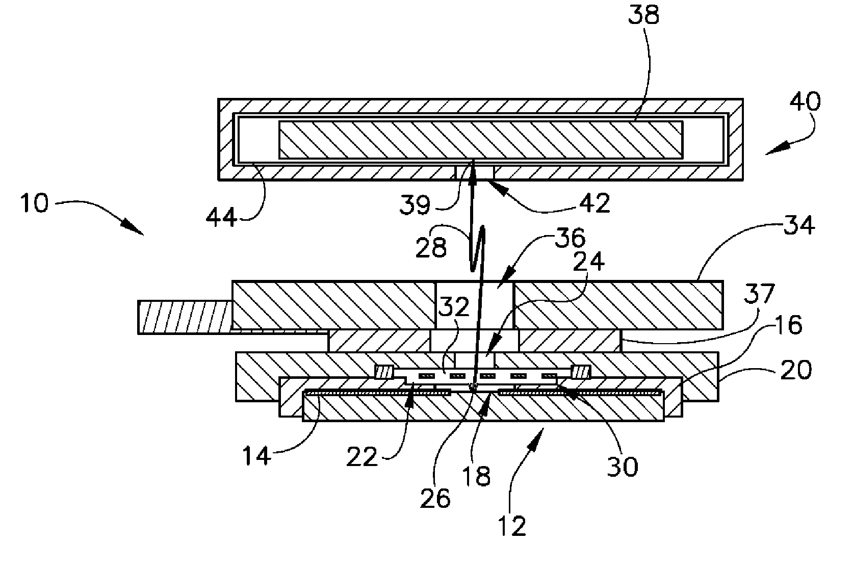
[0028]Referring to FIG. 1, a cross-sectional view of a single electron generator 10 is depicted according to one embodiment of the invention. As will be explained in greater detail be...


PUM


Abstract

A multiple spot x-ray generator is provided that includes a plurality of electron generators. Each electron generator includes an emitter element to emit an electron beam, a meshed grid adjacent each emitter element to enhance an electric field at a surface of the emitter element, and a focusing element positioned to receive the electron beam from each of the emitter elements and focus the electron beam to form a focal spot on a shielded target anode, the shielded target anode structure producing an array of x-ray focal spots when impinged by electron beams generated by the plurality of electron generators. The plurality of electron generators are arranged to form an electron generator matrix that includes activation connections electrically connected to the plurality of electron generators, wherein each electron generator is connected to a pair of the activation connections to receive an electric potential therefrom.

Description

BACKGROUND OF THE INVENTION[0001]The present invention relates generally to field-type electron emitters, and, more particularly, to a system for limiting the effects of arcing in field-type electron emitter arrays, focusing an electron beam generated by the emitter, and controlling individual emitters in an emitter array. A field emitter unit includes a protection and focusing scheme that functions to minimize degradation of the electron beam and allow for focusing of the electron beam into a desired spot size. A control system is provided that allows for individual control of field emitter units in an array with a minimum amount of control channels.[0002]Electron emissions in field-type electron emitter arrays are produced according to the Fowler-Nordheim theory relating the field emission current density of a clean metal surface to the electric field at the surface. Most field-type electron emitter arrays generally include an array of many field emitter devices. Emitter arrays ca...

Claims


Application Information

Patent Timeline
IPC IPC(8): H01J35/04H01J35/14
CPCH01J1/3048H01J2235/068H01J2235/062
Inventor ZOU, YUNVERMILYEA, MARK E.INZINNA, LOUIS PAULNECULAES, VASILE BOGDANPRICE, JOHN SCOTTCAO, YANGCAIAFA, ANTONIO
Owner GENERAL ELECTRIC CO
Why Eureka
Try Eureka