One-dimensional grid mesh for a high-compression electron gun

Active Publication Date: 2009-01-01
GENERAL ELECTRIC CO
View PDF6 Cites 8 Cited by
  • Summary
  • Abstract
  • Description
  • Claims
  • Application Information

AI Technical Summary

Benefits of technology

[0008]The present invention overcomes the aforementioned drawbacks by providing a cathode assembly that provides low voltage extraction and improved beam focusing. The cathode assembly incl

Problems solved by technology

Others have sought to incorporate field emitter (FE) arrays into cathode assemblies; however, in order to implement such a FE array into a cathode assembly, several issues have to be addressed.
While traditional mesh grids provide efficient low voltage extraction of t

Method used


Image

  • One-dimensional grid mesh for a high-compression electron gun
  • One-dimensional grid mesh for a high-compression electron gun
  • One-dimensional grid mesh for a high-compression electron gun

Examples


Embodiment Construction

[0025]The operating environment of the present invention is described with respect to a sixty-four-slice computed tomography (CT) system. While described with respect to a “third generation” CT scanner, the present invention is equally applicable with other CT systems. Additionally, it will be appreciated by those skilled in the art that the present invention is equally applicable for use with other applications in which an electron gun is implemented.

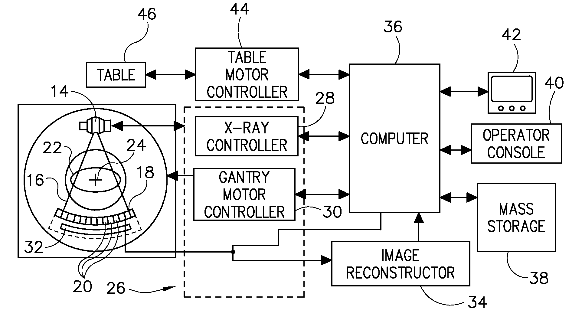
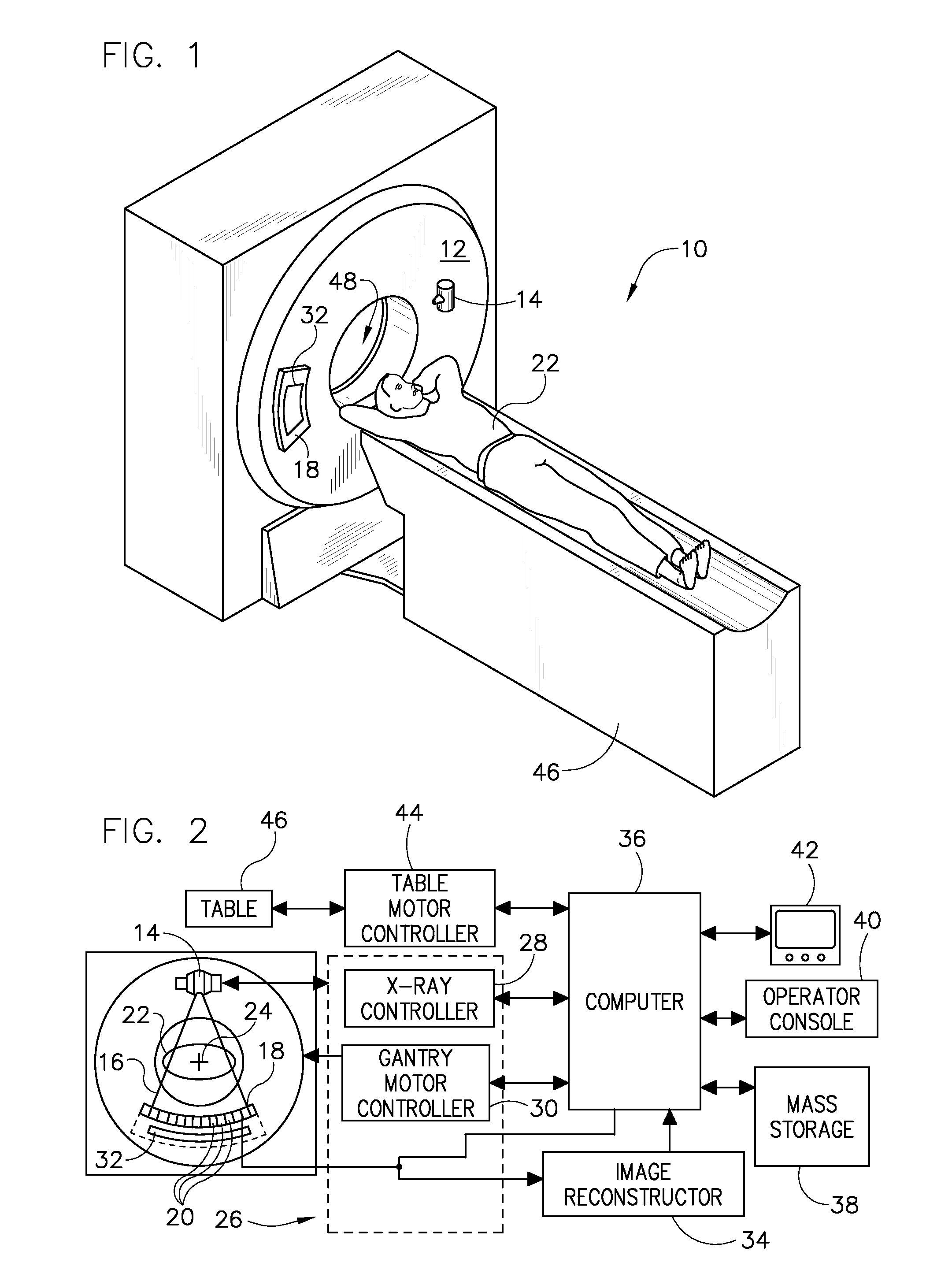
[0026]Referring to FIG. 1, a computed tomography (CT) imaging system 10 is shown as including a gantry 12 representative of a “third generation” CT scanner. Gantry 12 has an x-ray source 14 that projects a beam of x-rays 16 toward a detector assembly or collimator 18 on the opposite side of the gantry 12. Referring now to FIG. 2, detector assembly 18 is formed by a plurality of detectors 20 and data acquisition systems (DAS) 32. The plurality of detectors 20 sense the projected x-rays that pass through a medical patient 22, and DAS 32 ...


PUM


Abstract

A field emitter electron gun includes at least one field emitter cathode deposited on a substrate layer and configured to generate an electron beam. An extraction plate having an opening therethrough is positioned adjacent to the at least one field emitter cathode and is operated at a voltage so as to extract the electron beam out therefrom. A meshed grid is disposed between each of the at least one field emitter cathodes and the extraction plate. The meshed grid is configured to operate at a voltage so as to enhance an electric field at a surface of the at least one field emitter cathode. The meshed grid is a one-dimensional grid configured to focus the electron beam received from the at least one field emitter cathode into a desired spot size.

Description

BACKGROUND OF THE INVENTION[0001]The present invention relates generally to an electron optics scheme for generation of high frequency electromagnetic energy and, more particularly, to a method and apparatus for extracting an electron beam from a cathode while preserving beam quality.[0002]X-ray generating systems typically include an electron generating cathode and an anode in a sealed housing. The cathode provides an electron stream or current that is directed toward the anode. This focused electron beam is accelerated across the anode-to-cathode vacuum gap and produces x-rays upon impact with the anode. Because of the high power density generated at the location where the electron beam strikes the target, it is desirable to rotate the anode assembly. Many x-ray tubes therefore include a rotating anode structure for distributing the heat generated at a focal spot. The anode is typically rotated by an induction motor having a cylindrical rotor built into a cantilevered axle. The ax...

Claims


Application Information

Patent Timeline
IPC IPC(8): H01J35/00H01J29/48
CPCH01J1/304H01J2235/068H01J35/065
Inventor ZOU, YUNVERMILYEA, MARK E.
Owner GENERAL ELECTRIC CO
Why Eureka
Try Eureka