Belt type continuous variable transmission, power unit having the belt type continuous variable transmission, vehicle mounting thereon the belt type continuous variable transmission, and sheave for continuous variable transmission

a technology of transmission gear ratio and belt type, which is applied in the direction of gearing, transportation and packaging, hoisting equipment, etc., can solve the problems of not being able to achieve a predetermined minimum transmission gear ratio, not being able to avoid the proportion of outer peripheral surfaces of roller weights that contact the movable sheave body and the cam plate, etc., to suppress a change in speed ratio, reduce the transmission gear ratio, increase the transmission gear ratio ratio

Inactive Publication Date: 2010-09-28
YAMAHA MOTOR CO LTD
View PDF55 Cites 16 Cited by
  • Summary
  • Abstract
  • Description
  • Claims
  • Application Information

AI Technical Summary

Benefits of technology

[0013]It is an object of the invention to provide a belt type continuous variable transmission capable of suppressing a change in speed ratio at a minimum transmission gear ratio to a small amount.
[0016]It is a further object of the invention to provide a sheave for continuous variable transmissions, which is capable of suppressing a change in speed ratio at a minimum transmission gear ratio to a small amount.
[0022]In order to attain the object, a sheave for continuous variable transmissions, according to an embodiment of the invention, comprises a first sheave body, a second sheave body that forms between it and the first sheave body a belt groove, about which a belt is entrained. The second sheave body is enabled by a push body, which moves radially of the second sheave body according to centrifugal forces generated at the time of rotation of the second sheave body, to relatively slide in a direction toward and away from the first sheave body. Further, the second sheave body comprises a stopper that restricts movements of the push body by contacting with an outer surface of the push body when slid to a position of minimum transmission gear ratio, in which the belt groove is made smallest in width. The stopper is shaped to accelerate partial wear of the outer surface of the push body.
[0024]As a result, the belt groove is narrowed to cause a change in speed ratio in a direction, in which a decrease in transmission gear ratio is caused. In other words, it is possible to compensate for a variation in speed ratio in a direction, in which an increase in transmission gear ratio is caused. Accordingly, it is possible to suppress a change in speed ratio at a minimum transmission gear ratio to a small amount with simple measures, in which the stoppers are simply changed in shape.

Problems solved by technology

Therefore, when fresh roller weights are repeatedly pushed against the movable sheave body and the cam plate, those portions of outer peripheral surfaces of the roller weights, which contact with the movable sheave body and the cam plate, begin wear.
Accordingly, a diameter, at which the belt is entrained about the primary sheave, changes in a direction, in which a transmission gear ratio is increased, so that it is not possible to obtain a predetermined minimum transmission gear ratio.
Accordingly, with conventional belt type continuous variable transmissions, it is not possible to avoid a change in speed ratio in a direction, in which a minimum transmission gear ratio is increased, caused by wear of roller weights.
As a result, there is caused a problem of an increase in engine speed and a decrease in traveling speed of a motorcycle.

Method used


Image

  • Belt type continuous variable transmission, power unit having the belt type continuous variable transmission, vehicle mounting thereon the belt type continuous variable transmission, and sheave for continuous variable transmission
  • Belt type continuous variable transmission, power unit having the belt type continuous variable transmission, vehicle mounting thereon the belt type continuous variable transmission, and sheave for continuous variable transmission
  • Belt type continuous variable transmission, power unit having the belt type continuous variable transmission, vehicle mounting thereon the belt type continuous variable transmission, and sheave for continuous variable transmission

Examples


first embodiment

[0049]the invention will be described below with reference to FIGS. 1 to 16.

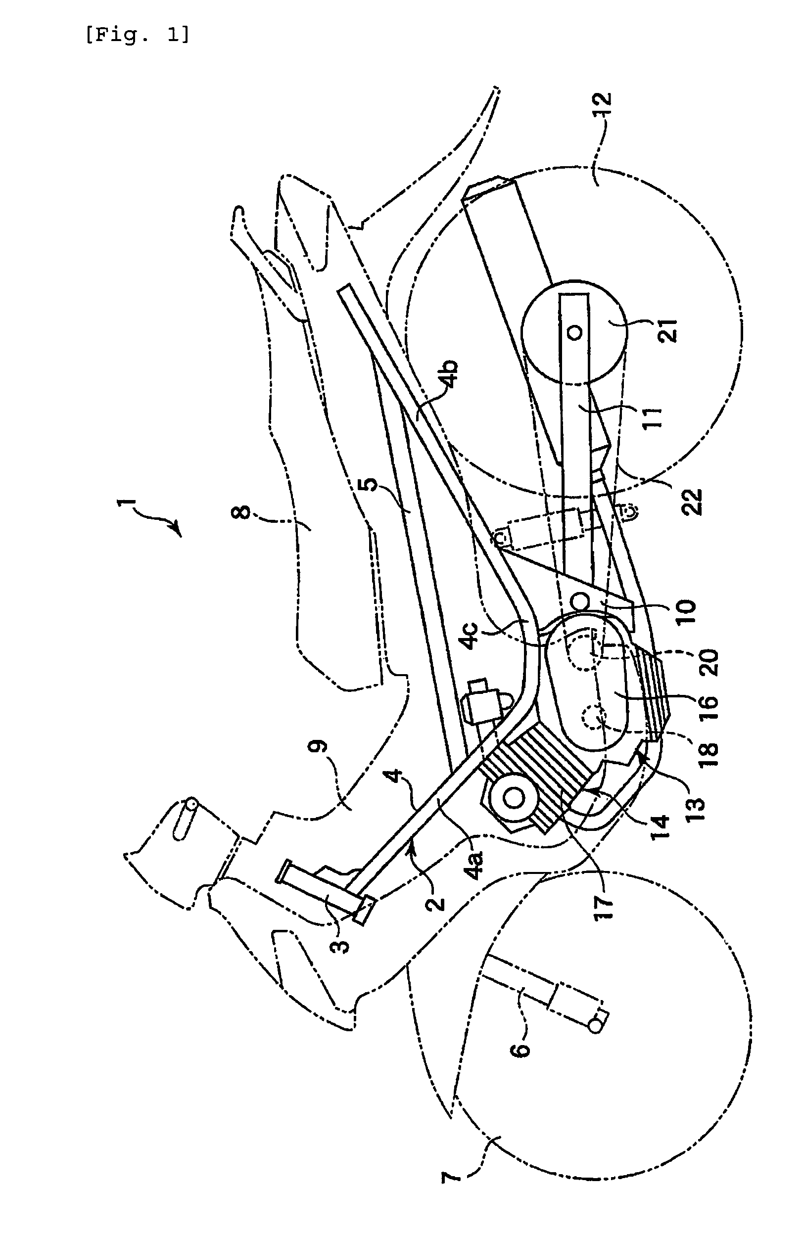
[0050]FIG. 1 discloses a motorcycle 1 exemplary of a vehicle according to the invention. The motorcycle 1 comprises a frame 2. The frame 2 includes a steering head pipe 3, a pair of main pipes 4 (only one of them is shown), and a pair of seat rails 5 (only one of them is shown). The steering head pipe 3 is positioned at a front end of the frame 2 and supports a front wheel 7 through a front fork 6.

[0051]The respective main pipes 4 extend rearward from the steering head pipe 3. The main pipes 4 comprise a front half 4a, a rear half 4b, and an intermediate portion 4c. The front half 4a extends obliquely downward from the steering head pipe 3. The rear half 4b extends obliquely upward from a lower end of the front half 4a. The intermediate portion 4c is positioned between the front half 4a and the rear half 4b.

[0052]The seat rail 5 bridges between the front half 4a and the rear half 4b of the main pipe 4. The ...

second embodiment

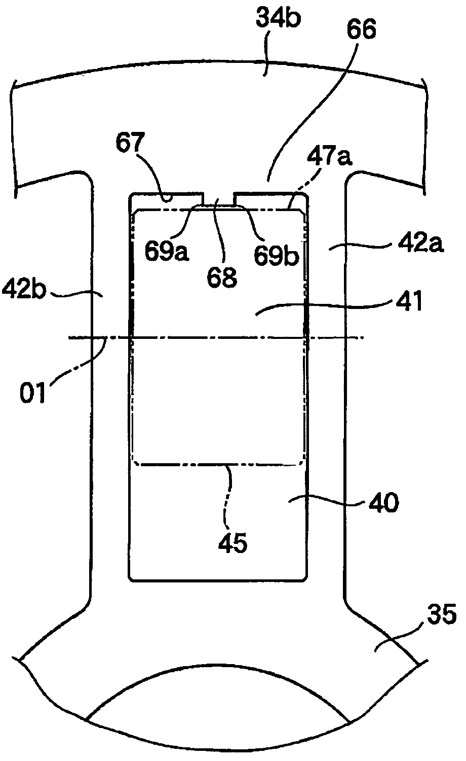
[0106]FIG. 17 shows the invention.

[0107]The second embodiment is different from the first embodiment in stoppers 66 on a second sheave body 34b. The second embodiment is the same as the first embodiment except the above. Therefore, the same constituents as those in the first embodiment are denoted by the same reference numerals as those in the latter, and an explanation therefor is omitted.

[0108]As shown in FIG. 17, a pair of projections 81, 82 are formed on a stopper surface 67 of the stopper 66. The projections 81, 82 are angular in shape to project toward the roller weight 45 from the stopper surface 67. The projections 81, 82 are separate from each other in an axial direction of the roller weight 45 and extend straight in a direction, in which the second sheave body 34b slides.

[0109]With such construction, the projections 81, 82 come into contact with outer surfaces 47a of the roller weights 45 when the second sheave body 34b has moved to a position to determine a minimum transm...

third embodiment

[0111]FIG. 18 shows the invention.

[0112]The third embodiment is different from the first embodiment in a shape of projections 91 that project from stopper surfaces 67. The third embodiment is the same as the first embodiment except the above.

[0113]As shown in FIG. 18, the projections 91 comprise an arcuately curved top 91a. The tops 91a are closest to the outer surfaces 47a of the roller weights 45. The tops 91a come into contact with the outer surfaces 47a of the roller weights 45 when the second sheave body 34b has moved to a position to determine a minimum transmission gear ratio. Such contact causes those portions of the outer surfaces 47a of the roller weights 45, which contact with the projections 91, to wear positively, and a state, in which the roller weights 45 bite into the projections 91, comes out. As a result, the roller weights 45 move radially outwardly of the second sheave body 34b. Accordingly, a change in speed ratio can be caused so as to decrease a transmission g...


PUM


Abstract

A belt type continuous variable transmission comprises a primary sheave, a secondary sheave, and a belt. The primary sheave comprises a first sheave body, a second sheave body that forms between it and the first sheave body a belt groove, about which a belt is entrained, a plurality of push bodies that slide the second sheave body according to centrifugal forces to change a width of the belt groove, and a plurality of stoppers that restrict movements of the push bodies by contacting with outer surfaces of the push bodies when the second sheave body reaches a position of minimum transmission gear ratio, in which the belt groove is made smallest in width. The stoppers are shaped to accelerate partial wear of the outer surfaces of the push bodies.

Description

TECHNICAL FIELD[0001]The present invention relates to a belt type continuous variable transmission, in which torque is transmitted to a secondary sheave from a primary sheave through an endless belt, and a sheave for continuous variable transmissions, and more particular, to a construction for prevention of a change in speed ratio at a minimum transmission gear ratio. Further, the invention relates to a power unit, in which, for example, an engine and a belt type continuous variable transmission are combined with each other, and a vehicle, such as motorcycles, mounting thereon a belt type continuous variable transmission.BACKGROUND ART[0002]For example, scooter type motorcycles mount thereon a belt type continuous variable transmission, of which transmission gear ratio can be adjusted in a stepless manner according to a traveling state. Belt type continuous variable transmissions comprise a primary sheave, a secondary sheave, and a belt. The belt is entrained between the primary she...

Claims


Application Information

Patent Timeline
Patent Type & Authority Patents(United States)
IPC IPC(8): F16H55/56F16H59/00F16H9/18F16H63/06
CPCF16G5/166F16H9/18F16H55/563F16H63/067
Inventor ISHIDA, YOUSUKE
Owner YAMAHA MOTOR CO LTD
Why Eureka
Try Eureka