Buck converter with inductor pre-energizing

a buck converter and inductor technology, applied in the direction of power conversion systems, electric variable regulation, instruments, etc., can solve problems such as battery voltage decline, and achieve the effect of simple control circuitry of buck-boost converters

Active Publication Date: 2010-09-28
DIALOG SEMICONDUCTOR GMBH
View PDF17 Cites 192 Cited by
  • Summary
  • Abstract
  • Description
  • Claims
  • Application Information

AI Technical Summary

Benefits of technology

[0016]A further object of the present invention is to avoid problems caused by a high duty cycle in the buck mode of buck-boost converters.
[0017]A further object of the present invention is to avoid problems caused by a low duty cycle in the boost mode of buck-boost converters.
[0018]Another object of the present invention is to achieve a simple control circuitry of a buck-boost converter.

Problems solved by technology

Additionally, the battery voltage declines as its stored power is drained.
It is a challenge to the designer of buck-boost converters to achieve converters providing a constant output voltage even during the interim phase.

Method used


Image

  • Buck converter with inductor pre-energizing
  • Buck converter with inductor pre-energizing
  • Buck converter with inductor pre-energizing

Examples


Embodiment Construction

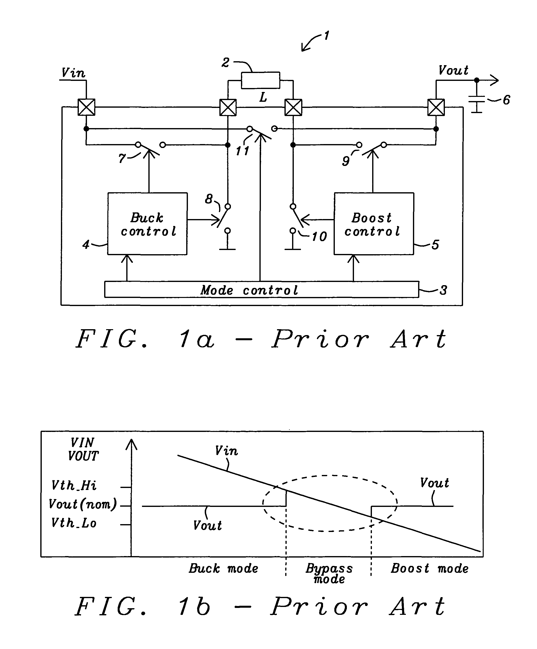
[0032]The preferred embodiments disclose methods and circuits for a buck-boost converter capable to achieve an output voltage being constant over all operation modes. The present invention especially solves the problem of output voltage variations if the input voltage is very close to the output voltage.

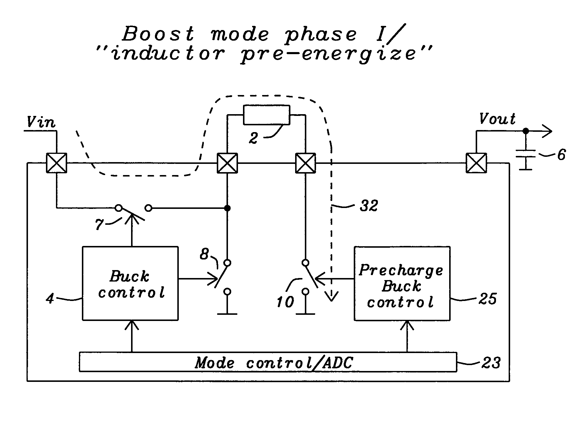
[0033]An important feature of the present invention is the pre-energization or pre-charging of the inductor of the buck-boost converter for a fixed part of the buck period in case the input voltage falls below a certain threshold or the buck duty cycle exceeds a maximum allowable level. After the pre-energization the normal buck control is exercised for the rest of the period.

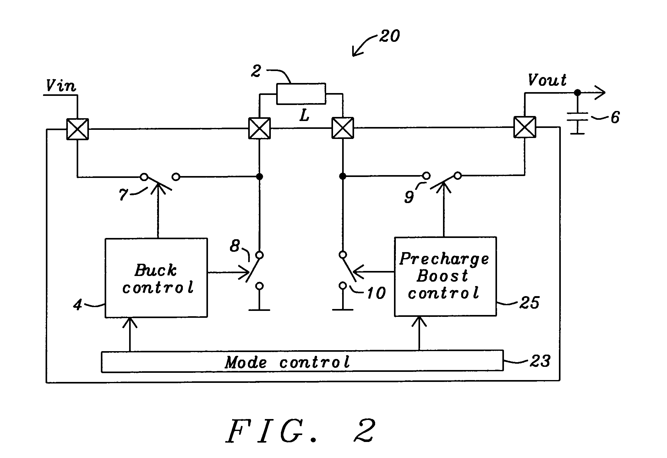
[0034]FIG. 2 shows a schematic illustration of a preferred embodiment of the present invention. A mode-control block 23 controls, depending upon the input voltage Vin, if the converter is operated in buck-mode or in a precharge mode followed by a buck mode, in which the energy stored in the inductor L2 during th...


PUM


Abstract

Circuits and methods to achieve a buck-boost converter, capable to achieve a constant output voltage by pre-charging of an inductor if the input voltage is close to the output voltage has been achieved. The prior art problem of output voltage variations occurring while the input voltage is close to the output voltage is avoided. In case the input voltage is lower than a defined threshold voltage or the duty cycle exceeds a defined maximum allowable level, the inductor of the converter is pre-charged followed by boosting of the energy of the inductor to the output of the converter. In both modes the control loops of the buck converter can be used for buck duty cycle control. The duration of the pre-charge depends upon the level of the input voltage, the lower the input level is the longer is the pre-charge performed.

Description

BACKGROUND OF THE INVENTION[0001](1) Field of the Invention[0002]This invention relates generally to DC-DC switch mode voltage converters and relates more specifically to a buck-boost voltage converter having a constant output voltage.[0003](2) Description of the Prior Art[0004]DC-to-DC converters are important in portable electronic devices such as cellular phones and laptop computers, which are supplied with power from batteries. Such electronic devices often contain several sub-circuits which each require unique voltage levels different from those supplied by the battery (sometimes higher or lower than the battery voltage, or even negative voltage). Additionally, the battery voltage declines as its stored power is drained. DC-to-DC converters offer a method of generating multiple controlled voltages from a single variable battery voltage, thereby saving space instead of using multiple batteries to supply different parts of the device.[0005]Electronic switch-mode DC-to-DC converte...

Claims


Application Information

Patent Timeline
Patent Type & Authority Patents(United States)
IPC IPC(8): G05F1/00
CPCH02M3/1582
Inventor BERTELE, MARTIN
Owner DIALOG SEMICONDUCTOR GMBH
Why Eureka
Try Eureka