Display driving circuit, display device, display system and method of driving display devices

a display driving circuit and display device technology, applied in the field of display devices, can solve problems such as deterioration of electromagnetic interference characteristics, increase of wiring complexity between the processor and the display driving circuit, and problems such as problems such as problems such as the effect of affecting the operation of the display devi

Inactive Publication Date: 2010-09-28
SAMSUNG ELECTRONICS CO LTD
View PDF8 Cites 12 Cited by
  • Summary
  • Abstract
  • Description
  • Claims
  • Application Information

AI Technical Summary

Problems solved by technology

However, problems may occur in an interface between a central processing unit (CPU) and a driving circuit for driving each of the display panels.
As the number of the display driving circuits is increased, the wiring complexity between the processor and the display driving circuits is increased and electromagnetic interference (EMI) characteristics may be deteriorated.
Accordingly, data throughputs that the processor has to process have been increased, causing more severe EMI problems.
Pixel data and control signals may be transferred through an MDDI interface or an 80-mode interface; however, the MDDI interface and the 80-mode interface may not transfer a video synchronization signal, or may have difficulty in transferring the video synchronization signal.
When the interface is a unilateral interface, there may be a tearing effect that degrades the video image displayed on the sub-display panel when the synchronization signal of the sub-display panel is not sent to the main display panel.
Thus, in the conventional dual display system, the complexity of the wiring and the EMI characteristics may not be effectively improved when the first display driver IC adopts the serial differential interface.

Method used


Image

  • Display driving circuit, display device, display system and method of driving display devices
  • Display driving circuit, display device, display system and method of driving display devices
  • Display driving circuit, display device, display system and method of driving display devices

Examples


Embodiment Construction

[0038]Hereinafter, exemplary embodiments of the present invention will be described with reference to the accompanying drawings. Like reference numerals refer to similar or identical elements throughout the description of the figures.

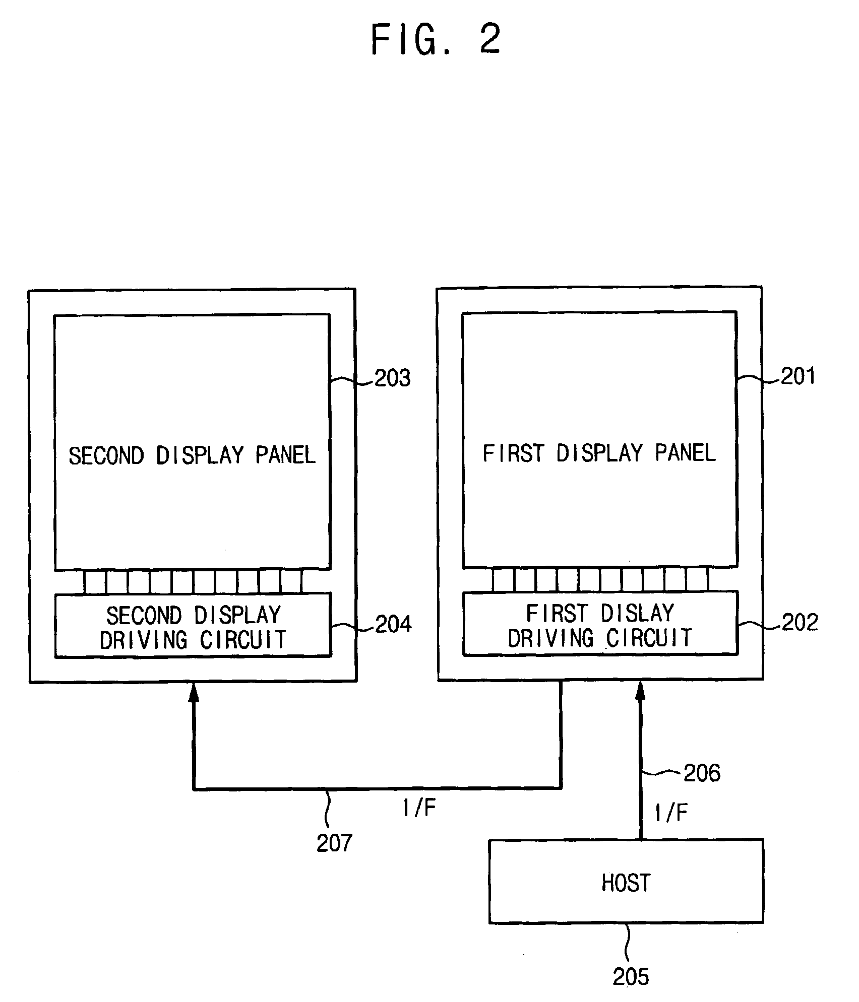
[0039]FIG. 2 is a block diagram illustrating a display system according to an exemplary embodiment of the present invention.

[0040]Referring to FIG. 2, the display system includes a first display panel 201, a first display driving circuit 202 for driving the first display panel 201, a second display panel 203, a second display driving circuit 204 for driving the second display panel 203 and a host 205. In a case when the display system is a mobile phone, the host 205 may be a base-band modem chip, such as for example, a mobile station modem (MSM) chip of Qualcomm, Inc., or another micro processing unit (MCU).

[0041]The first display driving circuit 202 may interface with two or more interfaces links represented by signal lines 206 and 207. The first displ...


PUM


Abstract

A display driving circuit includes a first interface unit, a signal discriminating circuit, a signal distributing circuit, a driver logic circuit and a synchronization processing unit. The first interface unit receives a first signal through a first interface from a host. The signal discriminating circuit discriminates whether the first signal corresponds to a first video signal or a second video signal. The signal distributing circuit divides the first signal into the first and second video signals based on a discrimination result of the signal discriminating circuit. The driver logic circuit drives a first display panel based on the first video signal. The second interface unit converts the second video signal into a second signal and provides the second signal through a second interface to an external display device. The synchronization processing unit receives a synchronization signal from the external display device and provides the synchronization signal to the host.

Description

CROSS-REFERENCE TO RELATED PATENT APPLICATION[0001]This application claims priority to Korean Patent Application No. 2005-84695, filed on Sep. 12, 2005, the contents of which are herein incorporated by reference in their entirety.BACKGROUND OF THE INVENTION[0002]1. Technical Field[0003]The present disclosure relates to display devices and, more particularly, to display driving circuits, display devices, display systems and methods of driving display devices for a multi-display system.[0004]2. Discussion of Related Art[0005]A display device comprising a dual display format includes a main display panel and a sub-display panel. The sub-display panel displays a relatively small amount of information compared to the main display panel.[0006]In the case of a folder type mobile phone, the main display panel, which is located inside of a folder cover, functions to display a phone number while dialing or an elapsed time of a phone call, etc. The sub display panel, which can be located in th...

Claims


Application Information

Patent Timeline
Patent Type & Authority Patents(United States)
IPC IPC(8): G09G5/00
CPCG06F3/1431G09G5/006G09G2330/022G09G2330/06G06F13/00G09G3/20G09G3/30G09G3/36
Inventor SONG, MIN-SEOKKIM, JONG-SEON
Owner SAMSUNG ELECTRONICS CO LTD
Why Eureka
Try Eureka