
Single mode optical fiber with improved bend performance

a single-mode optical fiber and bend performance technology, applied in the field of optical fibers, can solve the problems of high attenuation or even total darkening, affecting the optical and mechanical properties of the fiber, and affecting the performance of the fiber

Inactive Publication Date: 2010-09-28
WEATHERFORD TECH HLDG LLC
View PDF58 Cites 17 Cited by
  • Summary
  • Abstract
  • Description
  • Claims
  • Application Information

AI Technical Summary

Problems solved by technology

However, packaging and deployment of optical sensors frequently subjects the fiber to bending that can detrimentally affect both optical and mechanical properties of the fiber.
Furthermore, the fibers may include glass index-modifying dopants such as germanium and phosphorus that sensitize the glass leading to high attenuation or even total darkening when operating in harsh environments that expose the fiber to nuclear radiation and hydrogen.
Sensing applications in such harsh environments utilizing any prior available fiber suffer from one or both of these problems associated with the fiber.

Method used


Image

  • Single mode optical fiber with improved bend performance
  • Single mode optical fiber with improved bend performance
  • Single mode optical fiber with improved bend performance

Examples


Embodiment Construction

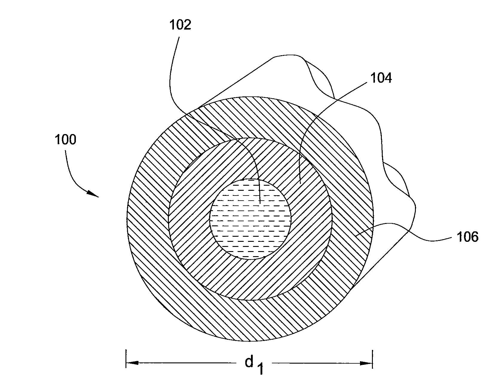
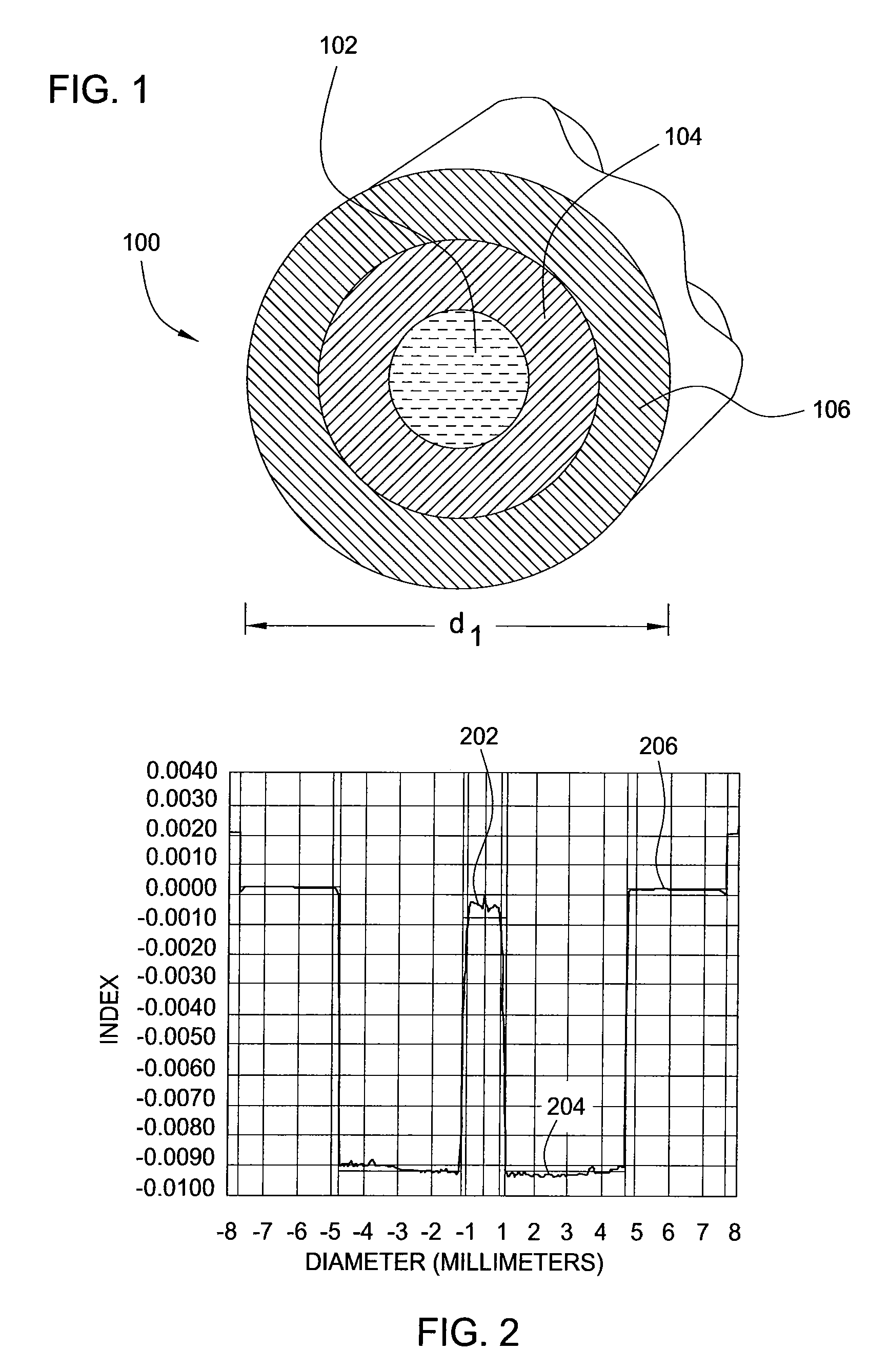
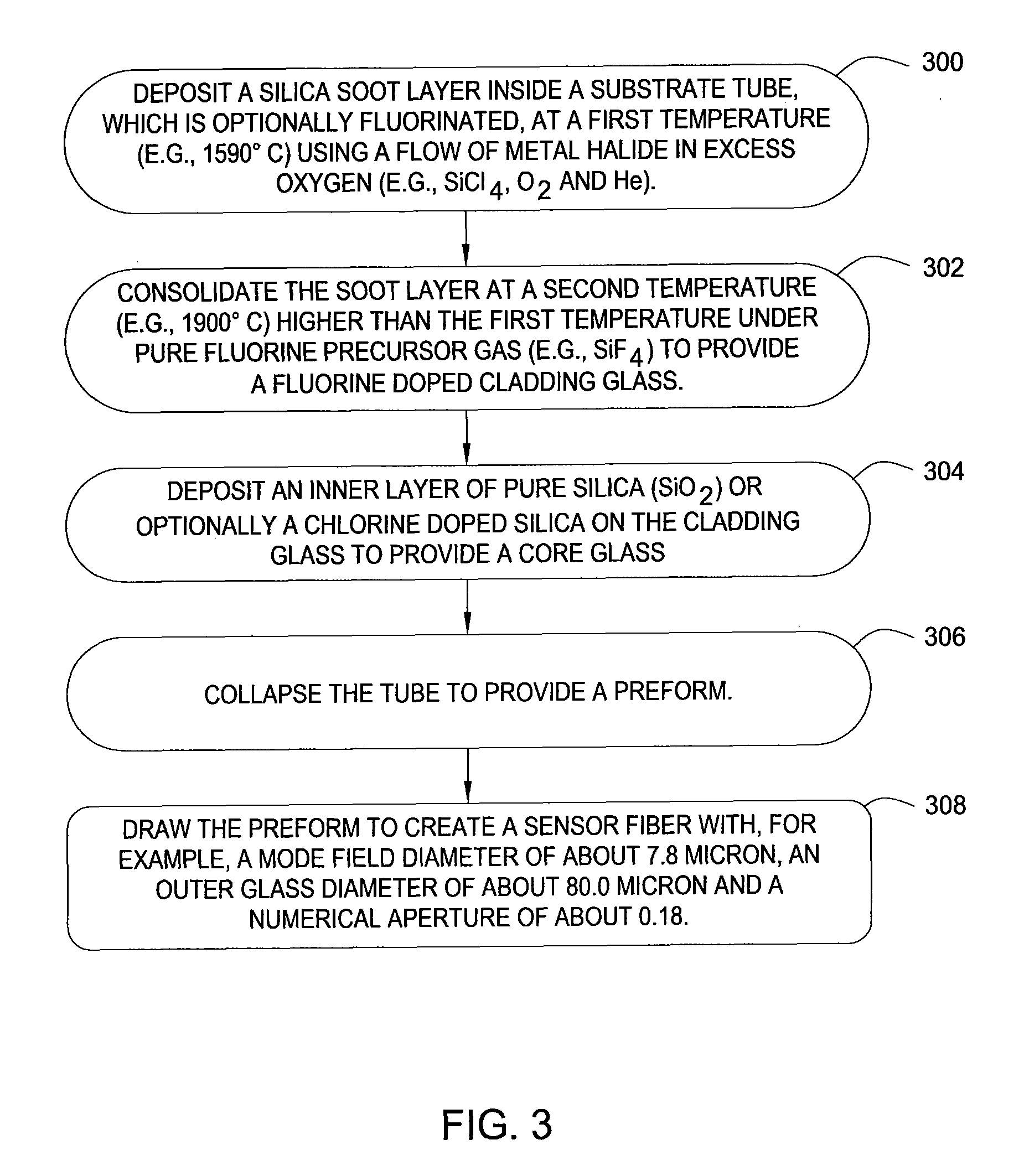
[0016]Embodiments of the invention relate to optical fibers suitable for use in sensing applications exposed to radiation environments. The fibers include a core of pure silica or chlorine doped silica surrounded by a fluorinated silica cladding. These glasses for the core and cladding utilize dopants that resist radiation-induced attenuation. A two step process for forming the cladding can achieve necessary concentrations of the fluorine by performing a soot deposition process in a different environment from a consolidation process where the soot is sintered into a glass. Concentration of fluorine doped into the cladding layer enables obtaining a numerical aperture that confines a mono-mode of the fiber to resist bend-induced attenuation. Dimensions of the fiber further facilitate bending ability of the fiber.

[0017]FIG. 1 shows a cross section of an optical fiber 100 with a core 102 for guiding light propagating through the fiber 100, a cladding layer 104 surrounding the core 102, ...


PUM

PropertyMeasurementUnit
refractive indexaaaaaaaaaa
diameteraaaaaaaaaa
diameteraaaaaaaaaa

Abstract

Methods and apparatus relate to optical fibers suitable for use in sensing applications exposed to radiation environments. The fibers include a core of pure silica or chlorine doped silica surrounded by a fluorinated silica cladding. These glasses for the core and cladding utilize dopants that resist radiation-induced attenuation. A two step process for forming the cladding can achieve necessary concentrations of the fluorine by performing a soot deposition process in a different environment from a consolidation process where the soot is sintered into a glass. Concentration of fluorine doped into the cladding layer enables obtaining a numerical aperture that confines a mono-mode of the fiber to resist bend-induced attenuation. Dimensions of the fiber further facilitate bending ability of the fiber.

Description

GOVERNMENT RIGHTS IN THIS INVENTION[0001]This invention was made with U.S. government support via the Navy under contract number N00173-04C-6024. The U.S. government has certain rights in this invention.BACKGROUND OF THE INVENTION[0002]1. Field of the Invention[0003]Embodiments of the invention generally relate to optical fibers that are suitable for use in sensing applications exposed to radiation environments.[0004]2. Description of the Related Art[0005]Interferometer and grating based optical sensors rely on light transmission through single mode optical fibers. A fiber optic gyroscope (FOG) exemplifies one type of sensor in which light is guided through a sensing coil of fiber and then detected to determine angular rotation of the FOG based on modulation of the light detected. However, packaging and deployment of optical sensors frequently subjects the fiber to bending that can detrimentally affect both optical and mechanical properties of the fiber. Furthermore, the fibers may ...

Claims


Application Information

Patent Timeline
Patent Type & Authority Patents(United States)
IPC IPC(8): G02B6/02
CPCC03B37/01853G02B6/03627G02B6/03605C03B2201/02C03B2201/20C03B2201/12Y02P40/57C03B37/014C03C13/045C03C25/104G02B6/02G02B6/03616
Inventor SANDERS, PAUL E.DOWD, EDWARD M.PIKE, BRIAN J.
Owner WEATHERFORD TECH HLDG LLC
Learn More