Clip

a clip and clip technology, applied in the field of clips, can solve the problems of vibration noise, also referred to as rattling, that can be experienced between, and achieve the effect of preventing vibration nois

Inactive Publication Date: 2010-10-05
TOYOTA MOTOR CO LTD
View PDF18 Cites 14 Cited by
  • Summary
  • Abstract
  • Description
  • Claims
  • Application Information

AI Technical Summary

Benefits of technology

[0005]The upper member also includes a catch stem located proximate to the leading edge of the upper member yet oppositely disposed across from the opening from the finger spring. The catch stem extends into the opening in a generally trailing edge direction and has a catch notch that faces the finger spring. In an embodiment of the present invention, the catch notch has a first surface that is generally parallel to the sheet located between the lower member and the upper member, a stop surface, and a cam surface extending from the first surface to the stop surface. The catch notch is operable to catch upon a sheet edge bounding an aperture within the sheet and thereby prevent removal of the sheet from the clip. The combination of the force applied against the leading edge of the sheet placed between the lower member and upper member of the clip and the catch notch affords for a variable retention system that prevents vibration noise between the sheet and the clip.

Problems solved by technology

Although such clips work well for attaching the instrument panel to the cowl, vibration noise, also referred to as rattling, can be experienced between the cowl, the clip and the instrument panel when the motor vehicle travels on a rough road.

Method used


Image

  • Clip
  • Clip
  • Clip

Examples


Embodiment Construction

[0013]The present invention discloses a clip that can be used to attach two objects to one another. As such, the present invention has utility as a clip and / or an attachment device.

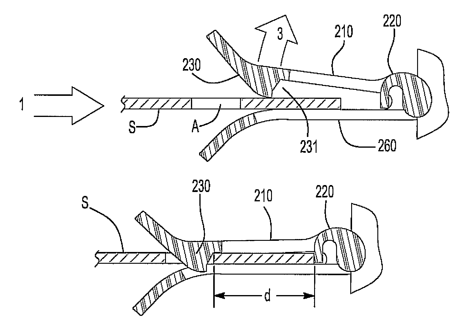
[0014]The clip of the present invention includes a variable retention system that affords for constant tension to be applied between the clip and a sheet placed therein. The constant tension applied to the sheet prevents vibration and / or rattling therebetween. The present invention uses a finger spring to apply tension to the leading edge of the sheet inserted within the clip and can include a catch mechanism that prevents the clip from being removed.

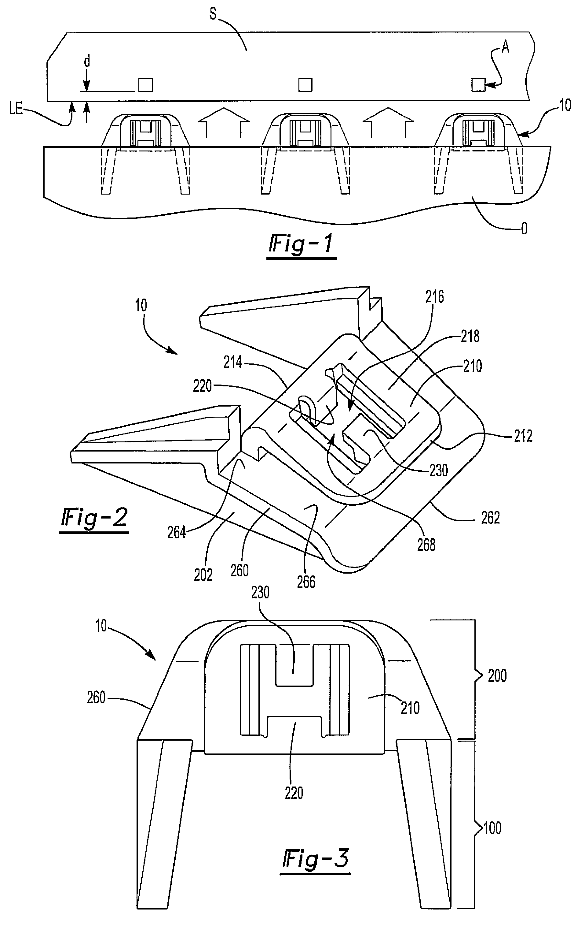
[0015]Referring now to FIG. 1, there is shown an embodiment of the present invention wherein an object O is attached to the clip 10, and the clip 10 is to be slid upon and attached to a sheet S. The sheet S has an aperture A that is spaced apart from the leading edge LE of the sheet S by a dimension d. Such a type of attachment between two objects is employed...


PUM


Abstract

The present invention discloses a clip for attaching an object to a sheet having an aperture spaced apart from a leading edge of the sheet. The clip includes a base with a generally planar lower member, the lower member having a leading edge and a trailing edge. The base also has a generally planar upper member extending across the lower member, the upper member also having a leading edge, a trailing edge and an opening between the upper member leading edge and trailing edge. The trailing edge of the upper member is attached to and extends from the base proximate the trailing edge of the lower member. The upper member also includes a spring located proximate to the trailing edge of the upper member and extending into the opening in a generally leading edge direction. The finger spring is operable to apply a force in a generally leading edge direction onto a sheet edge of a sheet inserted and located between the lower member and the upper member. The upper member can include a catch stem located proximate to the leading edge of the upper member yet oppositely disposed across from the opening from the finger spring. The catch stem extends into the opening in a generally trailing edge direction and is operable to catch a sheet edge of the sheet bounding the aperture spaced apart from the leading edge of the sheet and thereby preventing removal of the clip from the sheet.

Description

FIELD OF THE INVENTION[0001]This invention relates generally to a clip. More specifically, the invention relates to a clip with a variable retention system.BACKGROUND OF THE INVENTION[0002]A clip is generally used as a device for attaching one object to another. As such, clips have a multitude of uses and applications in a variety of industries. In the automotive industry, clips are used to attach various components of the interior of a motor vehicle to the frame and other support structures. For example, the instrument panel of a motor vehicle uses a clip to attach the panel to the cowl during assembly. Such a clip generally has one end that attaches to the instrument panel and another end that attaches to the cowl. The cowl, which is typically manufactured from sheet metal, will generally have a series of apertures that are spaced apart from the leading edge of the sheet metal, the aperture providing an attachment point for the clip. The clip is slid onto the sheet metal until a c...

Claims


Application Information

Patent Timeline
Patent Type & Authority Patents(United States)
IPC IPC(8): F16B5/06B62D25/08A44B99/00
CPCB60R13/0206F16B2/20B60R13/0256Y10T24/309Y10T24/307Y10T24/44026Y10T24/44F16B2005/0678
Inventor BABIAN, PHILIP JOSEPHWILLIAMS, PAXTON S.
Owner TOYOTA MOTOR CO LTD
Why Eureka
Try Eureka