Operating method for a Coriolis gyro, and evaluation/control electronics which are suitable for this purpose

a coriolis gyro and operating method technology, applied in the field of coriolis gyros, can solve the problems of high complexity of the electronic components of the evaluation/control electronics, difficult integration with other electronic components, and large electrical power requirements, and achieve low-cost and large-scale-miniaturized evaluation/control electronics

Active Publication Date: 2010-10-05
LITEF
View PDF13 Cites 28 Cited by
  • Summary
  • Abstract
  • Description
  • Claims
  • Application Information

AI Technical Summary

Benefits of technology

[0016]It is therefore an object of the invention to provide an operating method for a double-resonance Coriolis gyro that requires as few electronic components as possible (in particular analog / digital converters and digital / analog converters) whereby they can be produced with low-cost and large-scale-miniaturized evaluation / control electronics.

Problems solved by technology

A disadvantage of the arrangement is its high complexity in terms of the electronic components of the evaluation / control electronics.
They are expensive and require a large amount of electrical power.
The digital / analog converters frequently require a number of supply voltages and are difficult to integrate with other electronic components (in particular, digital components) restricting miniaturization.

Method used


Image

  • Operating method for a Coriolis gyro, and evaluation/control electronics which are suitable for this purpose
  • Operating method for a Coriolis gyro, and evaluation/control electronics which are suitable for this purpose
  • Operating method for a Coriolis gyro, and evaluation/control electronics which are suitable for this purpose

Examples


Embodiment Construction

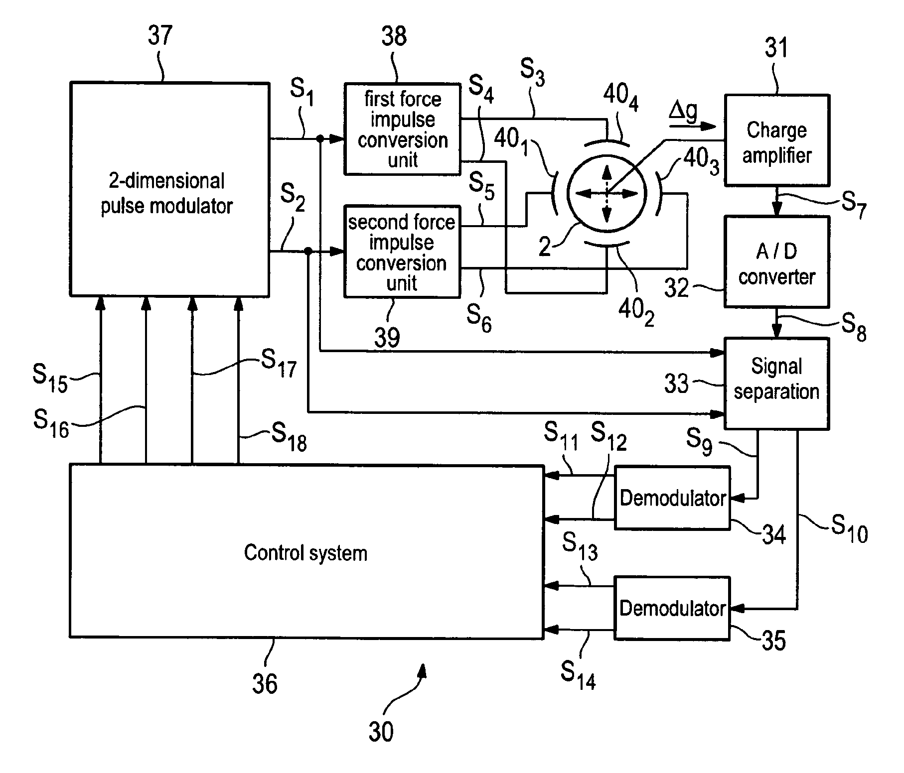
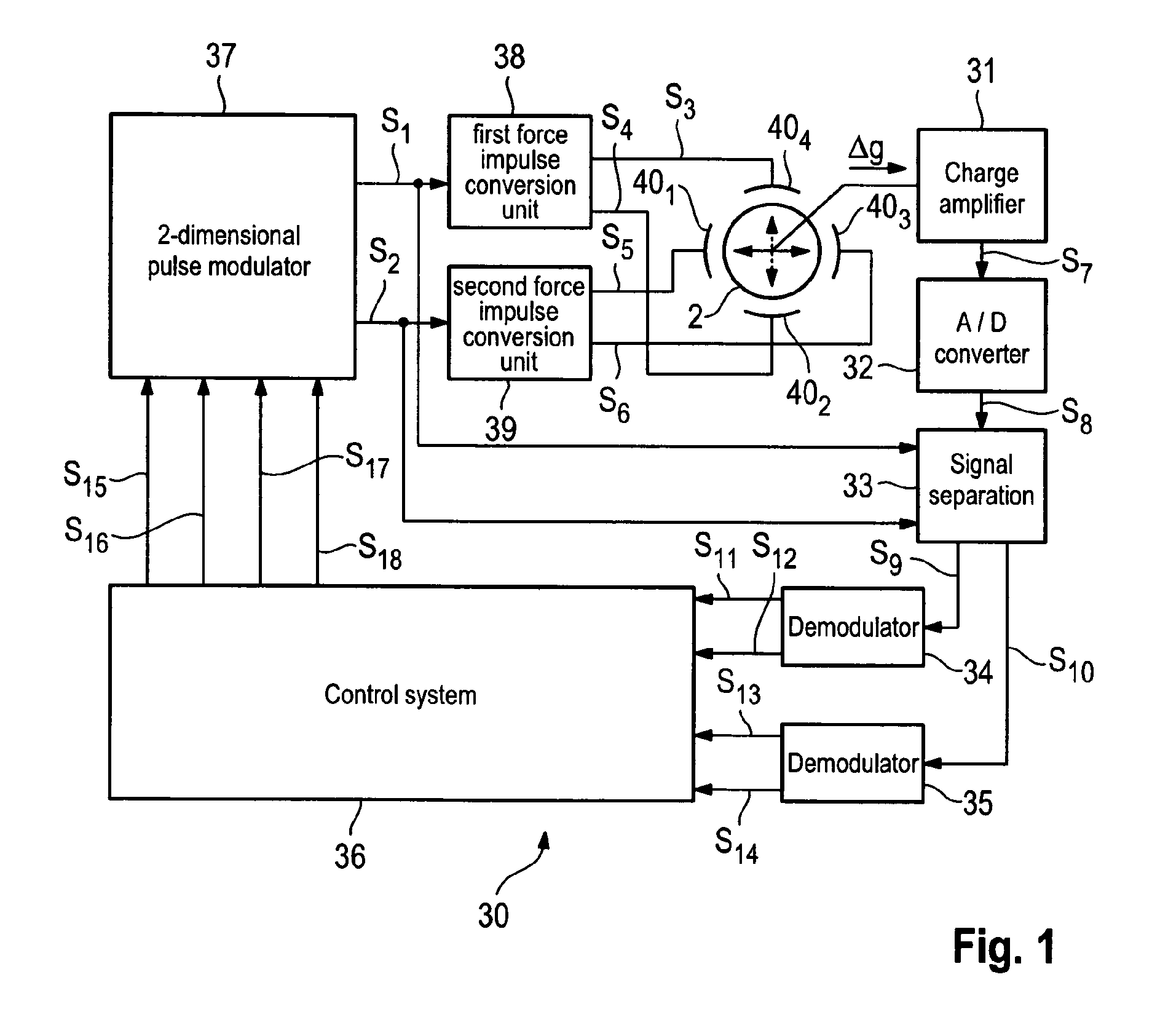
[0036]FIG. 1 is a schematic diagram of evaluation / control electronics 30 in accordance with the invention. It includes a charge amplifier 31, an analog / digital converter 32, signal separation 33, a first demodulator 34, a second demodulator 35, a control system 36, a two-dimensional pulse modulator 37, a first and a second force impulse conversion unit 38, 39 and a first to fourth force transmitter electrode 401 to 404. The assembly of the components identified by the reference numbers 31 to 40 forms two control loops, one for setting the amplitudes / frequencies of the stimulation oscillation, and the other for setting the amplitudes / frequencies of the read oscillation.

[0037]As can be seen, the circuit of the invention has a single analog / digital converter 32 and no digital / analog converters. The functions of digital / analog converters are performed by the combination of the two-dimensional pulse modulator 37 and the two force impulse conversion units 38, 39.

[0038]The method of operat...


PUM


Abstract

An operating method for a Coriolis gyro. Digital read signals are produced that represent a measure of the instantaneous amplitudes / frequencies of the stimulation oscillation / read oscillation of the gyro resonator. Force signals are applied to the resonator. The force signals are controlled as a function of the digital read signals so that the stimulation oscillation / read oscillation assume specific amplitudes / frequencies. The force signals are produced from quantized output signals from a pulse modulator. The modulator is fed with digital stimulation / compensation signals derived from the digital read signals.

Description

BACKGROUND[0001]1. Field of the Invention[0002]The present invention relates to Coriolis gyros. More particularly, the invention pertains to an operating method for a Coriolis gyro and to suitable evaluation / control electronics.[0003]2. Description of the Prior Art[0004]Coriolis gyros (also referred to as vibration gyros) are in increasing use for navigation. They include a mass system that is caused to oscillate with the oscillation generally being a superimposition of a large number of individual oscillations.[0005]The individual oscillations of the mass system are initially independent of one another, and may be regarded in abstract form as “resonators”. At least two resonators are required for operation of a vibration gyro; one (“first resonator”) is artificially stimulated to oscillate, with these oscillations being referred to below as a “stimulation oscillation”. The other (“second resonator”) is stimulated to oscillate only when the vibration gyro is moved / rotated. This is b...

Claims


Application Information

Patent Timeline
Patent Type & Authority Patents(United States)
IPC IPC(8): G01P9/04G01C19/56
CPCG01C19/56
Inventor SPAHLINGER, GUENTER
Owner LITEF
Why Eureka
Try Eureka