Environmental compressor protection assembly

a compressor protection and environmental technology, applied in the direction of auxillary lubrication, lubrication check valves, instruments, etc., can solve the problems of compressors and other industrial tools being seriously damaged or destroyed, the components of the lubrication system to fail, and the pressure increas

Active Publication Date: 2010-10-05
COMPRESSOR PROD INT
View PDF23 Cites 14 Cited by
  • Summary
  • Abstract
  • Description
  • Claims
  • Application Information

AI Technical Summary

Benefits of technology

[0010]An object of the invention is to provide protection against exces

Problems solved by technology

If a blockage occurs in the lubrication system, the positive displacement nature of the pump can cause a dramatic increase in the pressure in the lubrication system 100, which can cause components in the lubrication system to fail.
3. If the flow of lubricant is interrupted, compressors and other industrial tools can be seriously damaged or destroy
The resulting oil spill can be of significant size, is virtually impossible for the operator in the field to clean up, and raises environmental concerns.
Atmospheric rupture assemblies also raise safety concerns for workers in the area of the equipment.
The rupture of such assemblies has resulted in operators being struck by the high pressure lubricant and injured by pieces of the alumin

Method used


Image

  • Environmental compressor protection assembly
  • Environmental compressor protection assembly
  • Environmental compressor protection assembly

Examples


Embodiment Construction

[0026]Embodiments of the current invention eliminate environmental contamination from oil spills on compressor skids; protect compressor operators from possible injury caused by high pressure oil squirting from a blown rupture disc; prevent compressor component failure by opening at specified pressure; contain a visual indicator that notifies compressor operators of system overpressure conditions; remain in the open position until reset by an operator; and can be set to different opening pressures.

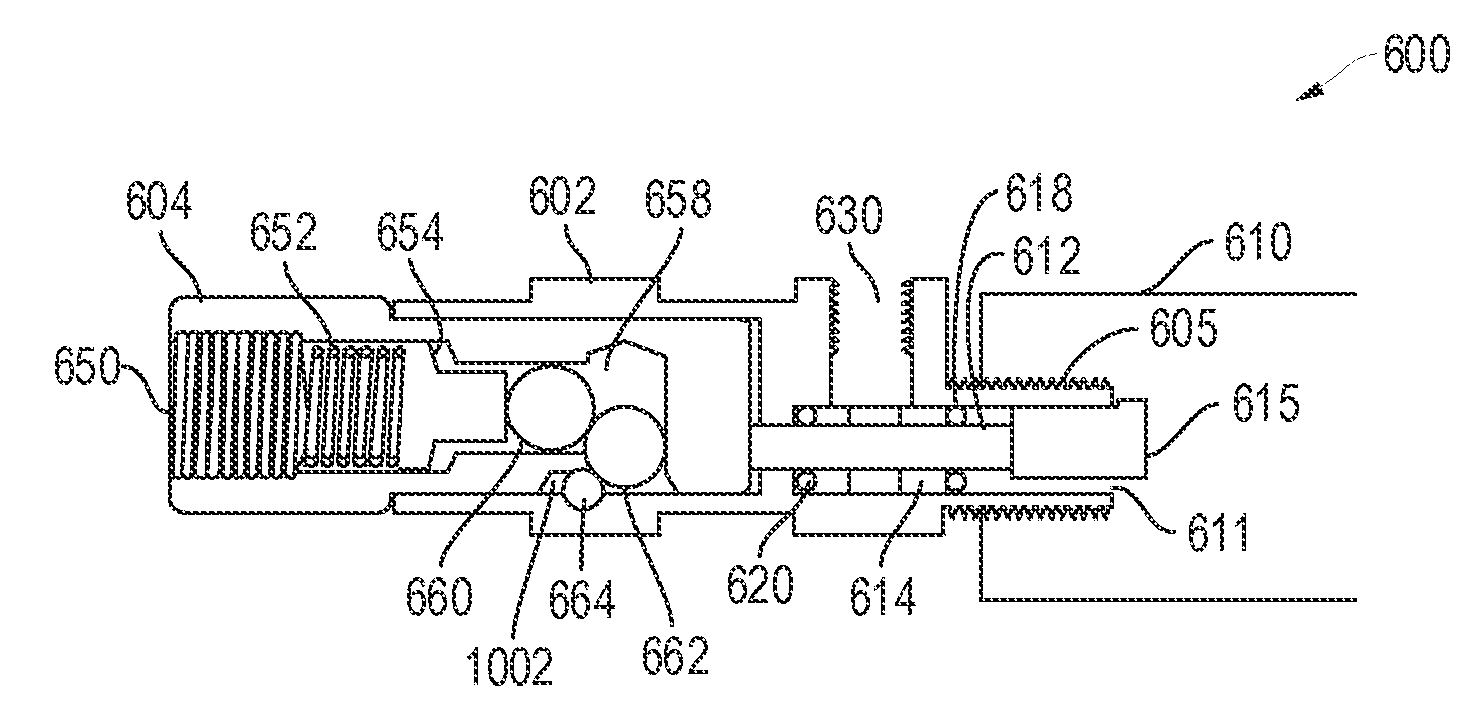
[0027]A typical embodiment of the pressure relief system is referred to as an Environmental Compressor Protection Assembly (“EPR™”) or a Pop Open Pressure Relief (“POPR™”) valve. Embodiments of the pop open pressure relief valve are typically used in lubrication systems that include positive displacement pumps and that provide a relatively low volume of lubricant at a relatively high pressure. During normal operation, a pop open pressure relief valve is closed. When a specified pressure is...


PUM


Abstract

A device that relieves lubricant pressure in a divider block lubrication system into a fluid reservoir, a container, or directly back into the compressor frame to which the tubing is connected. This eliminates housekeeping, environmental, safety, and compressor component failure concerns associated with current atmospheric rupture assemblies that relieve directly to the atmosphere. The environmental compressor protection assembly contains a spring set to a pre-determined pressure. Lubricant pressure in excess of this pre-determined set pressure results in spring compression and opening of a relief path. The assembly preferably remains in a full open position and must be must be manually reset to the closed position to prevent fluid flow in the system. A preferred assembly for maintaining the valve in either the open and closed position includes two balls, one of which remains trapped behind a pin during normal operation and is forced from behind the pin during an overpressure condition, the ball being prevented by the geometry of the housing from returning without manual intervention to its operating position. The relief path can lead to a fluid reservoir, a container, or directly back into the compressor frame. Flow of lubricant through the relief path results in loss of flow to the lubrication system. This triggers an alarm in the no-flow system and shutdown of the compressor. The relief path remains open until an operator resets the device. A visual indicator shows an operator if the relief valve is open or closed.

Description

[0001]This application claims priority from U.S. Provisional Patent Application No. 60 / 849,556, filed on Oct. 4, 2006, which is herein incorporated by reference.TECHNICAL FIELD OF THE INVENTION[0002]The present invention relates to pressure relief systems for positive displacement fluid distribution systems, such as high pressure, low volume systems used to deliver lubricant to natural gas compressors.BACKGROUND OF THE INVENTION[0003]Compressors and other machines use lubricants distributed by lubrication systems to reduce internal friction between parts by injecting the lubricant, such as oil or grease, into critical bearing surfaces and reciprocating parts junctions.[0004]FIG. 1 shows a schematically typical lubrication system 100 for natural gas compressors 101. Such systems typically include a high pressure, low volume, positive displacement oil pump 102 including a lubricator gear box 104 that drives multiple lubricator pump roller rocker assemblies 106. Fluid is supplied to th...

Claims


Application Information

Patent Timeline
IPC IPC(8): F01M1/16F01M1/18
CPCF16K17/042F16N7/385Y10T137/0324Y10T137/2647Y10T137/7738Y10T137/8326Y10T137/1774Y10T137/7734Y10T137/7838Y10T137/7922Y10T137/7925F01M1/16F16N13/22F16N29/00F16N13/02F16N23/00F16N29/04
Inventor ROYS, CURTISEASTON, MICHAEL
Owner COMPRESSOR PROD INT
Why Eureka
Try Eureka