Vacuum cleaner having agitator performing linear translation

a technology of linear translation and vacuum cleaner, which is applied in the field of vacuum cleaners, can solve the problems of disadvantages in the aspect of surface pressure generation, and inability to efficiently suck impurities, so as to reduce the minimum required lifting force, increase the surface pressure, and maximize the cleaning performance

Inactive Publication Date: 2010-10-12
LG ELECTRONICS INC
View PDF13 Cites 0 Cited by
  • Summary
  • Abstract
  • Description
  • Claims
  • Application Information

AI Technical Summary

Benefits of technology

[0007]An object of the present invention is to provide a vacuum cleaner which can maintain a high surface pressure which is an advantage of an ordinary type nozzle portion, and increase a drag coefficient of impurities.
[0008]In order to achieve the above-described object of the invention, there is provided a vacuum cleaner, including: a vacuum cleaner main body for supplying a suction force; a suction nozzle portion for sucking impurities by the suction force; a suction passage for connecting the suction nozzle portion to a suction pump; and an agitator installed at the suction passage, for performing linear translation. In this configuration, as the agitator is formed narrow and long, the bottom surface of the suction nozzle portion can maintain a small suction area. Therefore, the vacuum cleaner attains a high surface pressure which is an advantage of an ordinary type suction nozzle portion, and a high drag coefficient of impurities which is an advantage of a brush type suction nozzle portion.

Problems solved by technology

That is, the vacuum cleaner cannot efficiently suck the impurities due to an adhesion force between carpet hairs and impurity particles.
The power nozzle portion or the turbine type nozzle portion has a lower surface pressure than an ordinary type nozzle portion, and thus is disadvantageous in the aspect of the surface pressure generation.
However, in the case of a carpet to which impurities stick, a sum of an adhesion force A and an impurity weight G is larger than a lifting force F. It is thus impossible to efficiently suck the impurities.
A region between the brush bristles is relatively poorly cleaned.
If the transmission belt is used for a long time, it is broken, and thus replaced.
As a result, reliability of the product is reduced.

Method used


Image

  • Vacuum cleaner having agitator performing linear translation
  • Vacuum cleaner having agitator performing linear translation
  • Vacuum cleaner having agitator performing linear translation

Examples


Embodiment Construction

[0044]A vacuum cleaner having an agitator performing linear translation in accordance with the preferred embodiments of the present invention will now be described in detail with reference to the accompanying drawings.

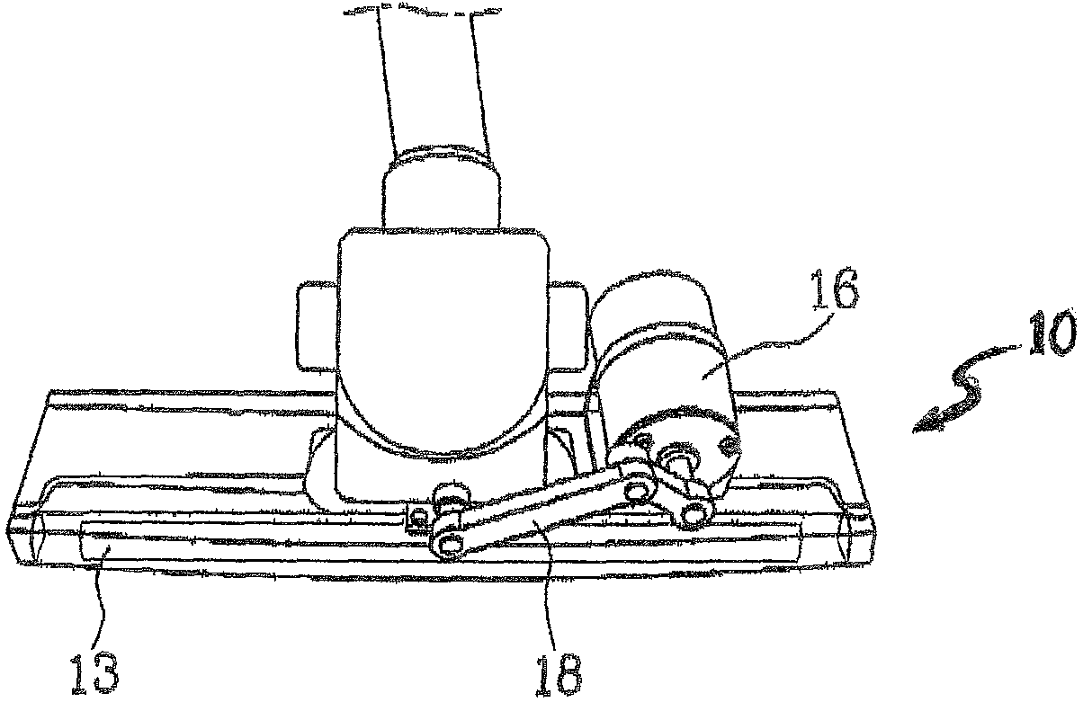
[0045]FIG. 6 illustrates a bottom surface of a suction nozzle portion in which an agitator is installed in accordance with the present invention. Generally, a vacuum cleaner includes a cleaner main body (not shown) in which a suction pump is installed, and a suction nozzle portion 10 for sucking impurities. The cleaner main body and the suction nozzle portion 10 are connected to each other by a suction passage so that the air can flow therebetween. A suction hole 12 opened to extend the suction passage to the bottom surface of the suction nozzle portion 10 is formed in the bottom surface of the suction nozzle portion 10. A vacuum channel 11 is formed narrow and long at the right and left sides of the suction hole 12 on the bottom surface of the suction nozzle portion 1...


PUM


Abstract

A vacuum cleaner is provided that includes a vacuum cleaner main body having a suction pump, a suction nozzle portion that sucks impurities by a suction force supplied by the suction pump, a suction passage that connects the suction nozzle portion to the suction pump, an agitator installed at the suction passage, and a driving device that makes the agitator perform a linear translation. As the agitator is formed narrow and long, a bottom surface of the suction nozzle portion may maintain a small suction area. Therefore the vacuum cleaner attains a high surface pressure which is an advantage of an ordinary type suction nozzle portion, and a high drag coefficient of impurities which is an advantage of a brush type suction nozzle portion.

Description

TECHNICAL FIELD[0001]The present invention relates to a vacuum cleaner, and more particularly, to a vacuum cleaner having an agitator performing linear translation at its suction nozzle portion.BACKGROUND ART[0002]A vacuum cleaner sucks the air containing impurities by a vacuum pressure generated by a vacuum motor installed in a main body, filters off the impurities in the main body, and collects and discharges the impurities.[0003]The vacuum cleaner sucks the air containing the impurities through a suction nozzle portion. The position of the suction nozzle portion must be continuously changed to clean a large area space. The cleaning performance of the vacuum cleaner is lower on a carpet than a floor. That is, the vacuum cleaner cannot efficiently suck the impurities due to an adhesion force between carpet hairs and impurity particles.[0004]Accordingly, a brush is installed at the suction nozzle portion of the vacuum cleaner, for lifting the impurity particles from the carpet hairs...

Claims


Application Information

Patent Timeline
Patent Type & Authority Patents(United States)
IPC IPC(8): A47L9/04
CPCA47L9/04A47L9/0483A47L9/02
Inventor CHONG, CHUNG-OOKJEONG, KEYONG-SEONHYUN, KIE-TAKCHO, SEONG-KOOHWANG, GEUN-BAECHOI, KYU-CHUNSHIN, JIN-HYOUKJANG, JONG-KYU
Owner LG ELECTRONICS INC
Why Eureka
Try Eureka