
Ink jet recording apparatus and ink jet recording method

a recording apparatus and ink jet technology, applied in the direction of resistance/reactance/impedence, electrographic process, instruments, etc., can solve the problems of reducing drying efficiency, increasing cost or size, and blunders that may occur before being dried, and achieve low water absorption. , the effect of high quality printing

Inactive Publication Date: 2010-10-12
SEIKO EPSON CORP
View PDF30 Cites 3 Cited by
  • Summary
  • Abstract
  • Description
  • Claims
  • Application Information

AI Technical Summary

Benefits of technology

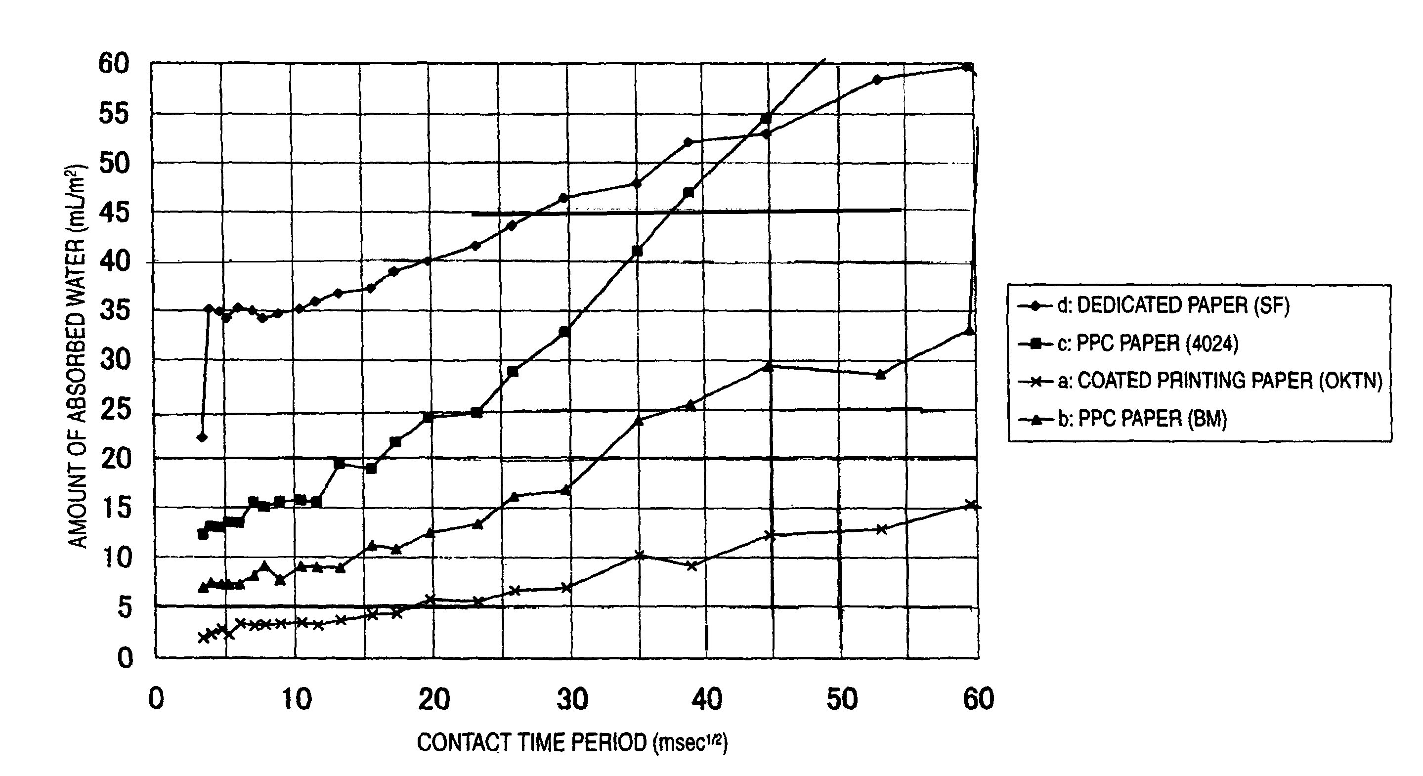
The invention provides an ink jet recording apparatus and method using an infrared ray heater that can practically be used in ink jet printing. The invention also provides a recording medium that can be used with low water absorbability, such as coated printing paper, without additional devices. The invention also provides a method for ejecting ink while heating the recording medium with the infrared ray heater to achieve a high quality image. The amount of ink ejected is about half of the amount required for conventional ink jet recording, but a clear image can still be formed. The invention also provides an image recorded on the recording medium using the described methods.

Problems solved by technology

However, in such an ink jet printer, since the pressure contact roller contacts the printing surface right after performing printing, a blur may occur before being dried.
Accordingly, the atmosphere temperature rises, so that even ink in the printing head is dried, which causes clogging.
In addition, the temperature of each component rises, a heat radiating mechanism needs to be provided in the printer, which results in an increase of a cost or size.
Since the temperature of the heater becomes the high temperature of 170° C., paper dust is dropped from the back face of the paper, which may cause a fire.
In addition, since the heating is performed from the back face of the printing surface, a drying efficiency is lowered, the printing head is always in a dried state by a hot air, and the clogging occurs.
In addition, in order to allow the ink absorbing layer to be transparent, fine powder silica or alumina is used as a raw material, which leads to an increase of a cost.
As a result, this increase of a cost becomes an obstacle that restricts a use of a user.
Although common paper such as copy paper or the like is cheap, since it has lower water absorbability than the above dedicated paper, it is not originally appropriate for the recording medium of the ink jet recording method.
Various ink has been developed for ensuring a high quality image with respect to the cheap common paper, but it is originally very difficult for the common paper to attain the image quality of the dedicated paper.
Since the coated paper has water absorbability lower than the common paper, it is not more appropriate than the common paper for the recording medium of the ink jet recording method.
However, according to this technology, since the image is not directly formed on the coated paper but formed using the intermediate transfer medium, a device other than an ink jet printer is further required.
That is, since a size of the printer increases and a manufacturing cost of the printer or a printing cost increases, it is not possible to achieve advantages of an ink jet recording method characterized by the simplicity and a small size.
However, according to this technology, the spraying of the image quality improving liquid may cause disadvantageous effects.
For example, clogging of nozzles may occur due to the mist of the image quality improving liquid.
Since a liquid amount on the recording medium may increase in order to spraying of the image quality improving liquid, it may not be possible to suppress bleed from occurring.

Method used


Image

  • Ink jet recording apparatus and ink jet recording method
  • Ink jet recording apparatus and ink jet recording method
  • Ink jet recording apparatus and ink jet recording method

Examples


Embodiment Construction

[0061]Embodiments of the invention will be described below in detail with reference to the accompanying drawings.

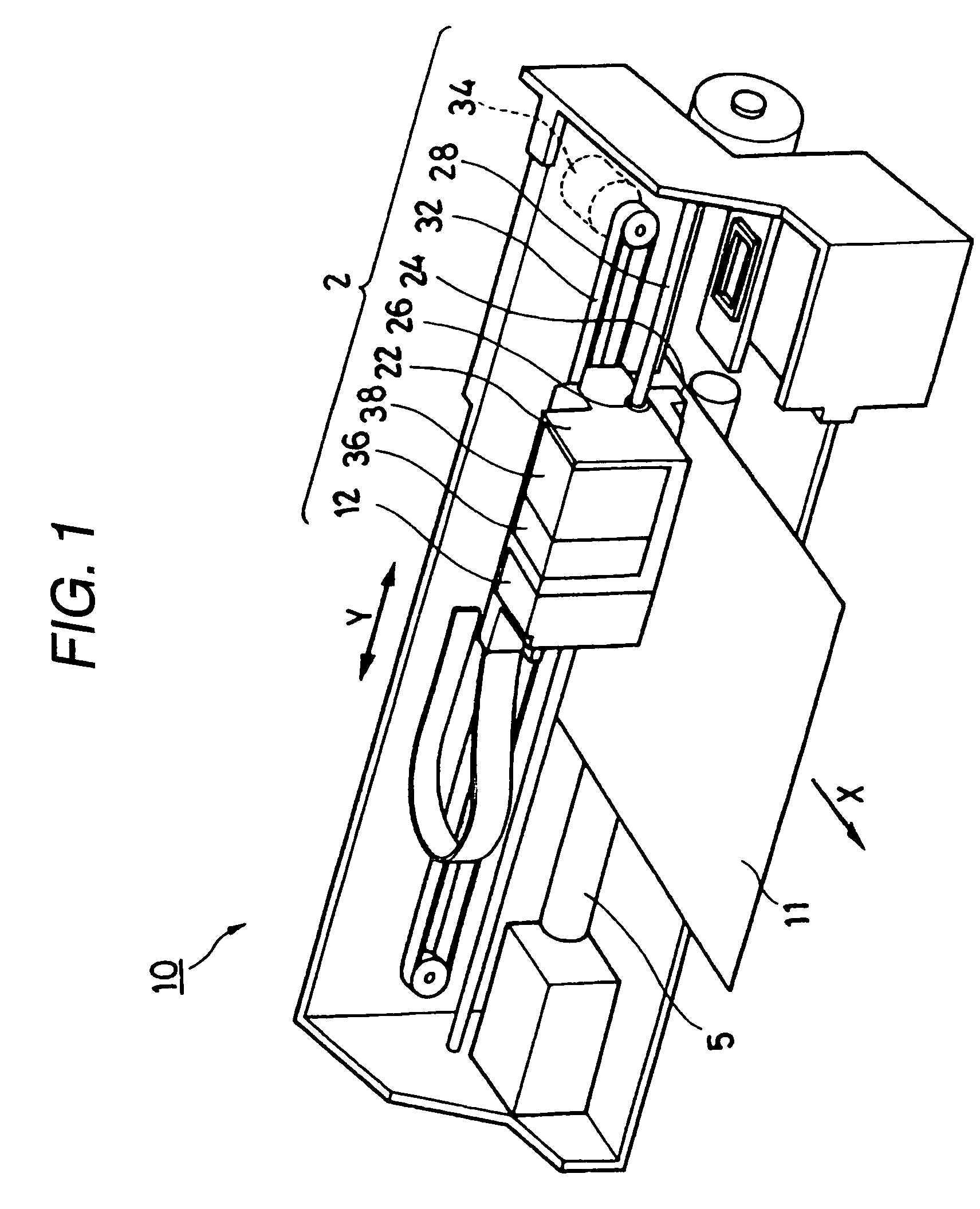
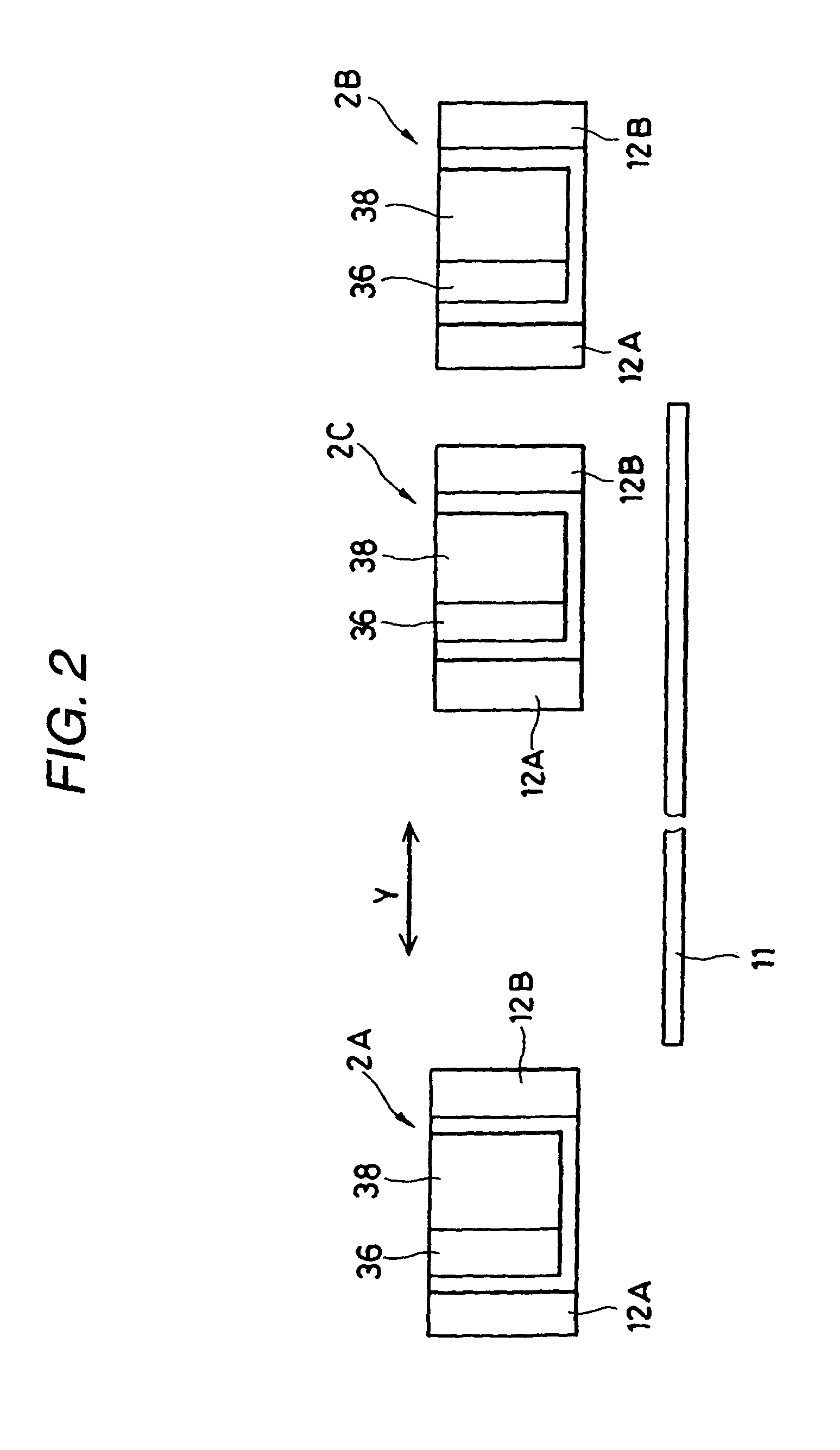
[0062]As shown in FIG. 1, an ink jet recording apparatus 10 according to one embodiment of the invention comprises a recording section 2. The recording section 2 includes a carriage 22 for mounting an ink cartridge, a recording head 24 for ejecting ink, a shaft hole 26 provided in the carriage 22, and a guide shaft 28 that is inserted into the shaft hole 26 for slidably supporting the carriage 22 in a direction shown by an arrow Y which is substantially perpendicular to a sheet feeding direction of a recording medium 11 such as paper shown by an arrow X. The recording head 24 has a plurality of nozzle orifices which are arrayed in the feeding direction X. The recording section 2 further includes a timing belt 32, a carriage motor 34, a black ink cartridge 36, and a color ink cartridge 38.

[0063]In this embodiment, an infrared ray heater 12 is provided in the carriage 22. T...


PUM


Abstract

A recording head is operable to eject ink toward a recording medium. A carriage mounting the recording head is operable to carry the recording head in a first direction. At least one infrared ray heater is provided on the carriage so as to oppose the recording medium. An input energy of the infrared ray heater is 60 W or less.

Description

BACKGROUND OF THE INVENTION[0001]The present invention relates to an ink jet recording apparatus and an ink jet recording method. Particularly, the invention relates to an ink jet recording apparatus provided with a heater, and to an ink jet recording method performed with respect to coated printing paper having low water absorbability.[0002]An ink jet recording method is a printing method which performs printing by ejecting minute ink droplets from a printing head toward a recording medium, such as paper or the like. Since the ink used in the ink jet recording method is ejected from the printing head, it is necessary for the ink to have low viscosity, and thus ink having high water content is used.[0003]Accordingly, as problems of the ink jet recording method, the occurrence of feathering, the occurrence of bleeding, the drop in density, the degradation in a color developing property, the degradation in fixing property (drying property), and the occurrence of a cockling curl may be...

Claims


Application Information

Patent Timeline
Patent Type & Authority Patents(United States)
IPC IPC(8): B41J2/01
CPCB41J11/002B41J11/00216
Inventor MATSUHASHI, KUNIHIKOOTA, HITOSHIMOMOSE, MASAYUKISANO, TSUYOSHITANOUE, TAKESHIKOGANEHIRA, SHUICHI
Owner SEIKO EPSON CORP
Learn More