Fuel vapor treatment device
a technology of fuel vapor treatment and treatment device, which is applied in the direction of machines/engines, separation processes, mechanical equipment, etc., can solve the problems of lowering the desorption efficiency, unable to effectively suppress the emission (bleeding) of fuel vapor to atmospheric air, and the non-uniformity of the desorption efficiency over the cross-sectional area of the gas passage, so as to promote the desorption of fuel vapor, enhance the desorption efficiency, and suppress the non-uni
- Summary
- Abstract
- Description
- Claims
- Application Information
AI Technical Summary
Benefits of technology
Problems solved by technology
Method used
Image
Examples
first embodiment
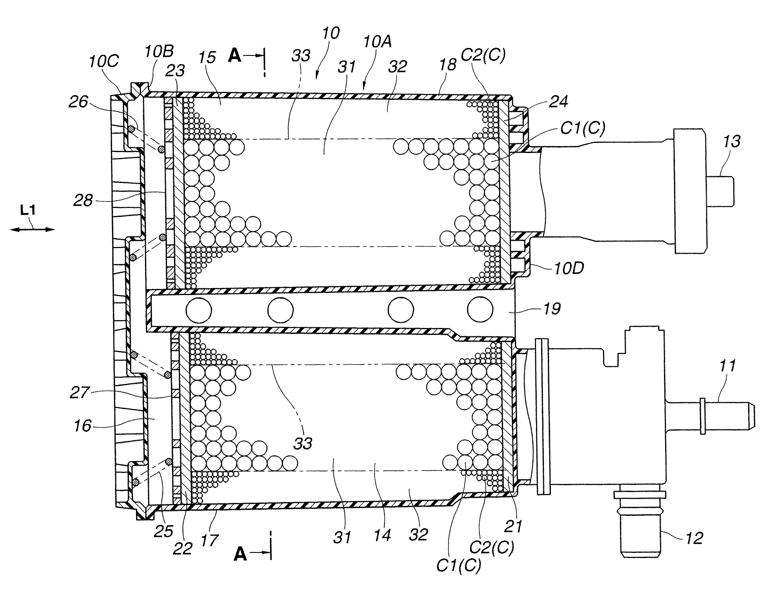
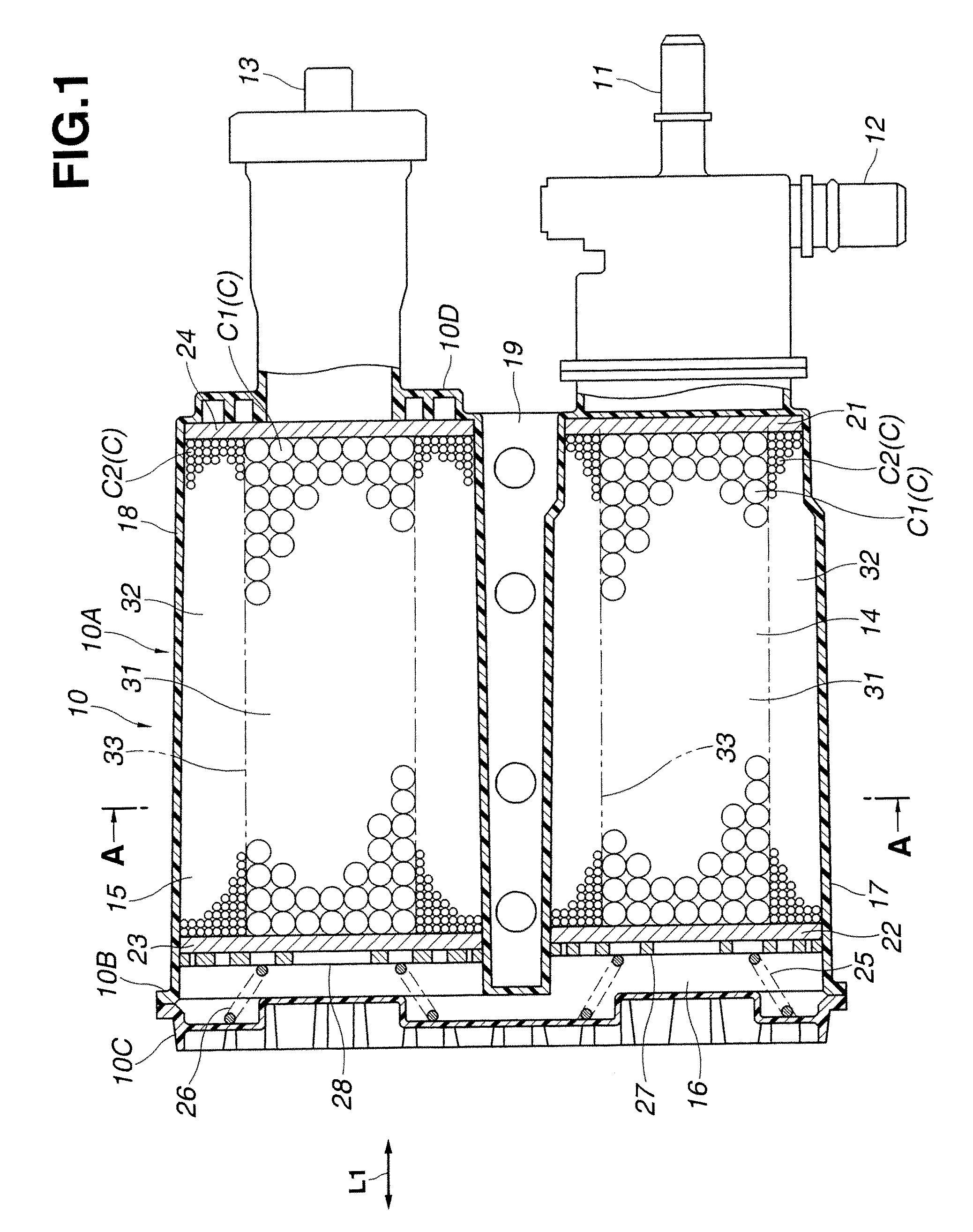
[0031]The desorption promoting structure of the canister according to the present invention is now explained. As shown in FIG. 1 and FIG. 2, the desorption promoting structure includes the first granular activated carbon (the first adsorbent) C1 filled in the central portion 31 of the cross-sectional area of each of the gas passages 14, 15 and the second granular activated carbon (the second adsorbent) C2 filled in the outer peripheral portion 32 of the cross-sectional area of each of the gas passages 14, 15, in which the first granular activated carbon C1 has a grain size (an average grain size) larger than that of the second granular activated carbon C2filled in the outer peripheral portion 32 of the cross-sectional area of each of the gas passages 14, 15 such that a void ratio in the central portion 31 becomes higher than that in the outer peripheral portion 32. In other words, the desorption promoting structure includes the granular activated carbon C1 filled in the central port...
third embodiment
[0041]Furthermore, in the desorption promoting structure of the canister according to the present invention, the size of each of the vent holes 30 (30A, 30B) of each of the grids 27, 28 is changed between the central portion of each of the grids 27, 28 which are opposed to the central portion 31 of the cross-sectional area of each of the gas passages 14, 15, and the outer peripheral portion of each of the grids 27, 28 which are opposed to the outer peripheral portion 32 of the cross-sectional area thereof. However, the vent holes 30 may be arranged to increase a total size or area of the vent holes 30 opposed to the central portion 31 of the cross-sectional area by increasing the number of the vent holes 30 opposed to the central portion 31 of the cross-sectional area without changing the size of each of the vent holes 30. That is, the vent holes 30 each having a same size may be arranged such that a density of the vent holes 30 opposed to the central portion 31 of the cross-section...
PUM
| Property | Measurement | Unit |
|---|---|---|
| grain size | aaaaa | aaaaa |
| size | aaaaa | aaaaa |
| temperature | aaaaa | aaaaa |
Abstract
Description
Claims
Application Information
 - R&D
- Intellectual Property
- Life Sciences
- Materials
- Tech Scout
- Unparalleled Data Quality
- Higher Quality Content
- 60% Fewer Hallucinations
Browse by: Latest US Patents, China's latest patents, Technical Efficacy Thesaurus, Application Domain, Technology Topic, Popular Technical Reports.
© 2025 PatSnap. All rights reserved.Legal|Privacy policy|Modern Slavery Act Transparency Statement|Sitemap|About US| Contact US: help@patsnap.com


